|
PART
|
COLOR
|
LOCATION
|
DIAGRAM
|
|
12 VOLT CONSTANT
|
GREEN (+)
|
IGNITION SWITCH HARNESS
|
|
|
STARTER
|
BLACK/RED (+) See NOTE *1
|
IGNITION SWITCH HARNESS
|
|
|
STARTER 2
|
BLACK/YELLOW (+) See NOTE *1
|
IGNITION SWITCH HARNESS
|
|
|
IGNITION 1
|
BLACK/RED (+)
|
IGNITION SWITCH HARNESS
|
|
|
IGNITION 2
|
N/A
|
|
|
|
IGNITION 3
|
N/A
|
|
|
|
ACCESSORY/HEATER BLOWER 1
|
RED (+)
|
IGNITION SWITCH HARNESS
|
|
|
ACCESSORY/HEATER BLOWER 2
|
WHITE/BLUE (+)
|
IGNITION SWITCH HARNESS
|
|
|
KEYSENSE
|
N/A
|
|
|
|
PARKING LIGHTS ( - )
|
N/A
|
|
|
|
PARKING LIGHTS ( + )
|
RED/BLUE (+)
|
IN DRIVERS KICK PANEL, HARNESS to REAR of VEHICLE
|
|
|
POWER LOCK
|
PINK (-) TYPE B, See NOTE *2
|
IN DRIVERS DOOR or @ BCM, PIN 37, BY FUSEBOX
|
|
|
POWER UNLOCK
|
BROWN (-) TYPE B, See NOTE *2
|
IN DRIVERS DOOR or @ BCM, PIN 44, BY FUSEBOX
|
|
|
LOCK MOTOR WIRE
|
YELLOW/RED (+)
|
@ BCM, PIN 30, BY FUSEBOX
|
|
|
DOOR TRIGGER
|
See NOTE *3
|
@ BCM, RIGHT OF THE FUSEBOX
|
14301_ALTIMA_(-) NEGATIVE DOOR PIN ISOLATION CIRCUIT.pdf
|
|
DOMELIGHT SUPERVISION
|
TURNS ON with UNLOCK
|
|
|
|
TRUNK RELEASE
|
RED/BLACK (-) or BLUE/RED (-)
|
@ BCM, PIN 76, BY FUSEBOX
|
|
|
SLIDING POWER DOOR
|
N/A
|
|
|
|
HORN
|
GREEN/WHITE (-)
|
@ STEERING COLUMN HANRESS
|
|
|
TACH
|
WHITE/GREEN (AC)
|
@ ECM, BEHIND GLOVEBOX, See NOTE *4
|
|
|
WAIT TO START LIGHT
|
N/A
|
|
|
|
BRAKE
|
RED/GREEN (+)
|
@ SWITCH ABOVE BRAKE PEDAL
|
|
|
FACTORY ALARM DISARM
|
WHITE/BLUE (-)
|
@ DRIVERS SWITCH IN DOOR
|
|
|
ANTI-THEFT
|
TRANSPONDER ANTI-THEFT SYSTEM
|
@ IGNITION BARREL
|
|
|
EXTRA INFORMATION
|
Show Large Image

To access the Under Dash wiring, you will first need to remove this Under Dash Panel, to do this remove the (2) Philips head screws on each corner at the Bottom of this panel.
Show Large Image

Before removing the Under Dash Panel you will need to remove this ring from around the Ignition Switch on the dash.
Show Large Image
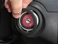
This Ring is just snapped into place and can be pried off.
Show Large Image

With the Ignition Switch Ring removed, you can now pull on each corner of the Under Dash Panel, this panel in snapped together on either end.
Show Large Image

With the Under Dash Panel lowered, unplug the Switch on this panel and remove the plug, this will let you remove the Under Dash Panel from the vehicle and set it aside.
Show Large Image

Next you will need to remove the Metal Knee Bolster, it is held into place by (2) 10mm bolts, remove the bolts and set this Metal pan aside.
Show Large Image

With the Ignition Switch attached to the dash, look up at the back of the Ignition Switch, you will see a Large WHITE Plug at the back of the switch, this plug contains the Ignition wires.
Show Large Image

This is a picture of the Male end of the NIS-1 T-Hanress plugged into the back of the Ignition Switch.
Show Large Image

This shows the (+) RED/GREEN BRAKE wire, marked with the RED Clip, at the BRAKE SWITCH, located at the BRAKE Pedal of the vehicle.
Show Large Image

This shows the (-) GREEN/WHITE HORN wire, marked with the RED Clip, in a harness wrapped with BLACK Wire Loom, running down from the Steering Cloumn of the vehicle.
Show Large Image

The (-) RED/BLACK TRUNK Release wire, marked with the RED Clip, is located in a Large WHITE Plug, under the Drivers Side of the dash, just behind the Hood Release.
Show Large Image

The (+) RED/BLUE PARKING LIGHT wire, marked with the RED Clip, is located in the Large Harness in the Drivers Kick Panel, heading to the Rear of the vehicle.
Show Large Image

In this picture the IGNITION SWITCH HARNESS Plug is removed from the Ignition Switch for the IDENTIFICATION of IGNITION wires. This Plug will only need removed from the Ignition Switch if you are installing the NIS-3 T-Harness.
|