|
PART
|
COLOR
|
LOCATION
|
DIAGRAM
|
|
12 VOLT CONSTANT
|
RED (+) and LIGHT GREEN/PURPLE (+)
|
@ IGNITION SWITCH HARNESS
|
|
|
STARTER
|
GREEN (+)
|
@ IGNITION SWITCH HARNESS
|
|
|
STARTER 2
|
N/A
|
|
|
|
IGNITION 1
|
WHITE/YELLOW (+)
|
@ IGNITION SWITCH HARNESS
|
|
|
IGNITION 2
|
PURPLE/ORANGE (+)
|
@ IGNITION SWITCH HARNESS
|
|
|
IGNITION 3
|
N/A
|
|
|
|
ACCESSORY/HEATER BLOWER 1
|
BLACK/LIGHT GREEN (+)
|
@ IGNITION SWITCH HARNESS
|
|
|
ACCESSORY/HEATER BLOWER 2
|
BLACK (+)
|
@ IGNITION SWITCH HARNESS
|
|
|
KEYSENSE
|
N/A
|
|
|
|
PARKING LIGHTS ( - )
|
N/A
|
|
|
|
PARKING LIGHTS ( + )
|
See NOTE *1
|
See DIAGRAM
|
28464_WINDSTAR_FREESTAR WINDSTAR PARKING LIGHT DIAGRAM.pdf
|
|
POWER LOCK
|
LIGHT BLUE/ORANGE (TYPE B)
|
@ FEM, 20 Pin PLug, See NOTE #3
|
|
|
POWER UNLOCK
|
LIGHT GREEN/YELLOW (TYPE B)
|
@ FEM, 20 Pin Plug, See NOTE #3
|
|
|
LOCK MOTOR WIRE
|
RED/ORANGE (+)
|
@ FEM, 26-Pin Plug, See NOTE #3
|
|
|
DOOR TRIGGER
|
BROWN/PINK (-) See NOTE #4
|
IN PASSENGERS D PILLAR, See DIAGRAM
|
14301_WINDSTAR_WINDSTAR DOOR PIN ISOLATION CIRCUIT.pdf
|
|
DOMELIGHT SUPERVISION
|
USE DOOR TRIGGER, (Requires Part #775 Relay)
|
|
|
|
TRUNK RELEASE
|
N/A
|
|
|
|
SLIDING POWER DOOR
|
WHITE/LIGHT GREEN (-)(Left Door) and GREEN/RED (-)(Right Door) See NOTE #6
|
@ OVERHEAD CONSOLE SWITCHES
|
|
|
HORN
|
ORANGE/RED (-)
|
@ FEM, 12 Pin Plug, See NOTE #3
|
|
|
TACH
|
See NOTE #5
|
@ IGNITION COIL PACK
|
|
|
WAIT TO START LIGHT
|
N/A
|
|
|
|
BRAKE
|
RED/LIGHT GREEN (+)
|
@ SWITCH ABOVE BRAKE PEDAL
|
|
|
FACTORY ALARM DISARM
|
LIGHT BLUE/BLACK (-)
|
@ FEM, 26 Pin Plug, See NOTE #3
|
|
|
ANTI-THEFT
|
FORD'S ANTI-THEFT, TRANSPONDER SYSTEM, SEE NOTE #1
|
@ IGNITION SWITCH TUMBLER
|
|
|
NOTES
|
NOTE #1: This vehicle MAY BE equipped with a Special Anti-theft key, to remote start you will
need a Bypass module 791, use this module IF you have a extra ignition key to
place inside the 791 to remote start, if you do not have an extra key to use or wish
not to have a key placed inside this bypass module, we OFFER a KEYLESS INTERFACE
BYPASS MODULE that does not require a key to be placed inside the bypass module,
this is Part # PKALL or PKFM, either one will work, to order, go to the INTERFACE
BYPASS MODULE PAGE on this website.
NOTE 2: This vehicle requires a Special Parking Light Daigram and 2 extra Relays part #775,
to connect, See DIAGRAM
NOTE #3: The FEM (Front Electronic Module) is located under the Drivers side of the
dash on the firewall.
NOTE #4: The BROWN/PINK wire must have a 1 AMP DIODE installed to prevent false alarms,
when connecting to an ALARM SYSTEM, to connect, See DIAGRAM
NOTE #5: The COIL PACK is located on the DRIVERS SIDE of the ENGINE, for TCH use
the PINK/WHITE, RED/LIGHT BLUE or BLUE/LIGHT GREEN
NOTE #6 the Sliding Doors on this vehicle are a (-)Negative type and there is a wire for each
door, to connect will require a Relay part # 775 for each door.
|
|
EXTRA INFORMATION
|
Show Large Image

This shows the IGNITION SWITCH HARNESS Plug with the GRAY Cover removed to expose the IGNITION SWITCH wires for IDENTIFICATION.
Show Large Image

To gain access to the under dash wire harness on this vehicle, you must remove the Plastic under dash panel and then this Metal Knee Bolster.
Show Large Image

After removing the Under Dash panels, you will next need to remove the LOWER Steering Column Cover, to do this will require you to remove the TILT WHEEL LEVER first. This lever is threaded in to the release arm in the column, it will just un-screw. After
Show Large Image

This shows the Lower Steering Column Cover and the Tilt Wheel Lever removed for the column. This must be done to get to the Factory TRANSPONDER Anti-theft System on this vehicle.
Show Large Image

When doing a TRNSPONDER BYPASS System, you will need to now remove the IGNITION SWITCH TUMBLER, to do this you will need to press in on the IGNITION SWITCH TUMBLER Release pin, in this picture you can see this release, it looks like a Ball-Bearing at the
Show Large Image

After the Ignition Switch Tumbler is removed, you can pull up on the UPPER Steering Column Cover. This will then expose the Factory Transponder Ring around the Ignition Switch. You will place the 791's TRANSPONDER LOOP ANTENNA around this ring.
Show Large Image
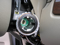
This shows the 791's TRANSPONDER LOOP ANTENNA in place around the IGNITION SWITCH and held in place with a wire tie to keep it thight against the Transponder Ring Antenna.
Show Large Image

The IGNITION SWITCH Harness is located on the LEFT side of the Steering Column and can be seen in this picture with the GRAY Protective cover over top of the Main BLACK Plug.
Show Large Image

This shows the IGNITION SWITCH HARNESS Plug removed from the IGNITION SWITCH Plug on the Steering Column, this is only done if you are adding a T-HARNESS part FD-1, to remove this plug, requires a 8mm socket, untighten the bolt and the plug will pull righ
Show Large Image

The PARKING LIGHT Switch on this vehicle is attached to the bezel and will just pull off of the dash as shown to get to the Harness Plugs on the back.
Show Large Image

With the HEADLIGHT SWITCH removed from the dash, you can see the (2) plugs on the back of this switch. The GRAY Plug on the left hand side of this switch will contain the (3) wires needed for the Parking Lights on this vehicle.
Show Large Image

This picture shows the (3) PARKING LIGHT wires marked with the RED Clip in the GRAY plug on the back of the Headlight Switch, to do parking Lights on this vehicle will require extra Relays Part #775 See DAIGRAM.
Show Large Image

This is a picture of the BRAKE Switch located above the Brake Pedal on this vehicle, the (+) RED/LIGHT GREEN BRAKE wire is seen in this picture at the switch in this (2) wire harness.
Show Large Image

This shows the FEM Module or FRONT ELECTRONIC MODULE that is located up under the Drivers side of the dash, next to the Fusebox.
Show Large Image

This shows the (-) LIGHT BLUE/BLACK FACTORY ALARM DISARM wire marked with the RED Clip, in the harness plug at the FEM Module.
Show Large Image

This shows the (-) ORANGE/RED HORN wire marked with the RED Clip, in the harness plug at the FEM Module.
Show Large Image

This shows the (TYPE B) LIGHT BLUE/ORANGE LOCK wire marked with the RED Clip, in the harness plug at the FEM Module.
Show Large Image

This shows the (TYPE B) LIGHT GREEN/YELLOW UNLOCK wire marked with the RED Clip, in the harness plug at the FEM Module.
|