Many 2003-2004 Forester XS and XT owners are experiencing
erratic operation of their Automatic Climate Control Systems (CCS). I have
tried several experiments, and came up with a solution that has greatly impoved the system
on my 2004 XT. I now keep the temperature dial in one setting (~71-72) and
the CCS maintains nearly stable cabin temperature at all times, without overheating and overcooling.
What causes this problem? I made some observations,
and figured out that the Climate Control System was very erratic because it
could not read the changes in cabin temperature fast enough. By the time a
change registered, the cabin was either too hot or too cold. Then the CCS would
switch gears and the temp would swing in the opposite direction. This would
continue ad infinitum.
The cause for this is lack of airflow to the cabin temp sensor inside the dash
by the ignition key. Subaru uses a Venturi tube to get cabin air to flow
through the sensor. The Venturi is powered by the Heater/AC fan. It
works somewhat OK in hot weather for cooling, because the air in the cabin is
hotter (high pressure) than the cooled AC air (low pressure) flowing through the
Venturi. The difference in pressure allows some air to flow to the sensor.
In cold weather, on the other hand, the cold air inside the
cabin (low pressure) barely makes its way to the sensor because the heated air
flowing through the Venturi (high pressure) almost completely stops the airflow.
It takes a very long time for the cabin air to make its way inside the tube to
affect the sensor.
Also, Venturi works best when the Heater/AC fan is on the
highest speed. As the fan speed decreases, the Venturi suction is
decreased proportionally. There is plenty of information on the web about
Venturi / Bernoulli principles.
Therefore, the system performs somewhat acceptably (not
perfectly) in the summer, but completely fails to maintain comfortable
temperature in the winter.
The solution, apparently, is to force cabin air over the
sensor so that the entire CCS reacts quickly and adjusts the temperature within
a range of 1-3 degrees instead of 7-12 degrees which I measured initially.
I built an assembly with a 12 V fan in it to run
continuously, regardless of the Venturi or the cold / hot air pressure
differential. The Aspirator Hose hooks up to the CC-Fix assembly, and the
Venturi gets taped up - it is no longer needed. This results in constant
and stable airflow over the temperature sensor, which in turn forces the CC
system to react to slightest changes in temperature.
Unlike the original fix,
which made some noise, this one is very quiet. It's not completely silent,
but it is barely perceptible. You will not notice it's there and working.
Here are some reviews from several people that
have ordered the kit from me.
I no longer make these kits due to the fact that I have been extremely busy and building these kits is time consuming, however, I still have three kits that I can sell to anyone who's interested. The
only tools required for installation are a Philips screwdriver, a 10mm socket, and duct tape.
No cutting or splicing. Could be easily removed and everything restored to
original state if desired. If you would like to build it yourself, here is
the parts list.
Contact me if you have questions or would like to order the kit.
Latest News
12/11/2007 - Hello all. Sorry I haven’t been active online for a long time, but I’d like to present some additional information.
First, I temporarily took down my CC-Fix web site because (A) I simply
haven’t had the time to build and sell these kits anymore and (B) the
web site kept getting hacked – Yahoo security is pathetic.
Second, I still have three kits left over in case anyone would like one.
Third, I have some additional points to share and hopefully shed some light on Subaru’s demonic climate control.
I have been driving around with a temperature probe mounted next to the
temp sensor grille opening for some time now. Here are my observations
concerning the heating operation.
1. The temp sensor is actually very accurate. Once the system finally
settles, the temperature at the probe is usually within 1-2 degrees of
set temperature. When set at 72, for example, the probe fluctuates in
the 71-74 degree range.
2. The standard airflow over the sensor is very poor. The fan kit improves that significantly, but, read the next item.
3. The area around the sensor grille opening has relatively inert air,
meaning there isn’t much air movement in the space around the ignition
switch, and the air sampled by the sensor is not truly representative
of the general mix of air in the cabin.
4. The initial blast of heat on high fan speed continues until the
sensor reaches approximately 10 degrees below desired setting during
daylight and about 8 degrees at night. For example, when set at 72, the
highest fan speed kicks down a notch when the sensor reads around 62-63
degrees during the day. This is also an example of the solar sensor
functionality – slightly more heat at night, less in daytime. I think
this calibration is too aggressive. In my opinion, the system should
kick down around 15-18 degrees within desired setting. Not much can be
done here without reprogramming the climate control computer’s
algorithm.
5. Also, within 10 degrees of set temperature, the air coming out of
outer dash vents becomes progressively lower in temperature until the
desired temperature is read by the sensor.
6. The system has the ability to output different temperature air at
different zones. Let’s refer to these as the Floor Zone and the Dash
Zone. There is also the defroster and side defrosters. Each one can
also have its own individual temperature. For simplicity, let’s focus
on the Floor and Dash zones.
7. The system is poorly calibrated in one respect such that the Dash
zone outputs too much air during the heating cycle. A normal system
should pump more air out of the Floor vents and a minimal amount
through the Dash vents, but that is not the Subaru way.
8. The sensor grille slats are tilted down. This means that the sensor
temperature reading is biased to the area slightly below the sensor.
Basically, it is biased to taking readings from the Floor zone over the
Dash zone. Since the system is improperly balanced, the Dash zone puts
out too much air, resulting in excessive heat at the torso and face
level, before the Floor zone can catch up and the sensor can react.
9. During long drives, the car eventually becomes cold inside. This is
due to the system overshooting its mark in the beginning at the Dash
zone. After the Floor zone is caught up to the desired temperature, the
general mix of air in the car is too warm, and the system tries to
compensate by providing cooler air at the Dash zone. Since the Floor
zone is now at the right temperature, and the sensor reading is biased
towards the floor zone, the system doesn’t know that the Dash zone
temperatures are now too cold at the face and torso level.
Some solutions implemented and being considered.
1. The CC-Fix fan kit. This has greatly improved the system operation
by providing a more powerful air flow over the temp sensor. However,
this does not fix the problems fully due to the poor system calibration
and biased temp readings from the Floor zone.
2. Temp sensor relocation. I have considered this. I was thinking of
mounting the sensor inside the steering column, drilling some holes in
the column housing, and using a small fan to blow the air over the
sensor. This would result in the sensor being a lot closer to the torso
and face and representing a better reading of what the occupant is
actually experiencing. I’m holding off on this for now, because it’s
pretty involved, and I’m not sure there is enough room inside the
column housing to fit all the parts.
3. System recalibrating / reprogramming. This would involve taking
apart the control module, removing the microcontroller, reverse
engineering the code, re-flashing with new code, and reassembling
everything back. Too much work for me.
4. Altering the sensor bias. I am experimenting with this currently. I
mounted a small angled flap made of clear plastic over the sensor which
forces it to take air reading slightly above the grille opening. This
seems to have improved the system operation further in that the initial
blast of heat is slightly shorter in duration, and on longer drives,
the car does not get as cold. I did this only a couple of weeks ago and
will post further observations once I’ve had a chance to go on a trip
of at least 50-75 miles in truly cold weather (teens or 20’s).
I hope this information provides some help to the many frustrated
Forester owners. Even more so, I hope someone at Subaru comes across
this web page and makes some use of it. Judging by their climate
control systems and weak batteries, I don’t think Subaru does much cold
weather testing.
01/08/2007 - Sorry for the long delay in updates.
Finally got word that the fix DOES work in the 2005+ Legacy / Outback. The
mounting and hookup is different than the Forester, and some custom tubing is
required. Unfortunately, I don't have pictures except this one on the Legacy / Outback page.
01/23/2006 - I am getting numerous inquiries regarding
using this fix on Legacy and Outback. If anyone has a Legacy / Outback,
lives near Northern NJ, and would like to use their car as a guinea pig, please
contact me.
01/12/2006 - All kits made starting in January 2006 now
have a high output Mag-Lev fan rated at 9 CFM. Also, noise reduction is
now achieved using self-stick felt strips inside the box. Fiberglass
insulation is no longer used. I am also using 2 AMP fuses from now on.
12/19/2005 - Due to numerous inquiries about buying the
kits directly on the web, an online order form with
pricing is now available. You will be redirected to the PayPal website for
secure order processing using a credit card or a PayPal account.
03/15/2005 - This is a detailed discussion on a Subaru
enthusiast site -
Scoobymods
- about this kit. A lot of informattion and excellent installation photos.
01/10/2005 - On all the kits built since January 2005, I started using a
6.9 CFM fan instead of a 4.8 CFM fan. The higher airflow will draw more
air to the temp sensor quicker, regulating the system even better. The
noise penalty is 2.0 db according to specs - 25.5 db for the new fan vs. 23.5 db
for the older model. The 2 db increase is not noticeable.
Detailed Instructions
This is the actual CC-Fix assembly.
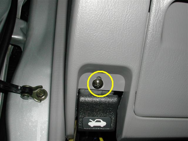
Step 1 - Remove the screw at lower left of under-dash panel.
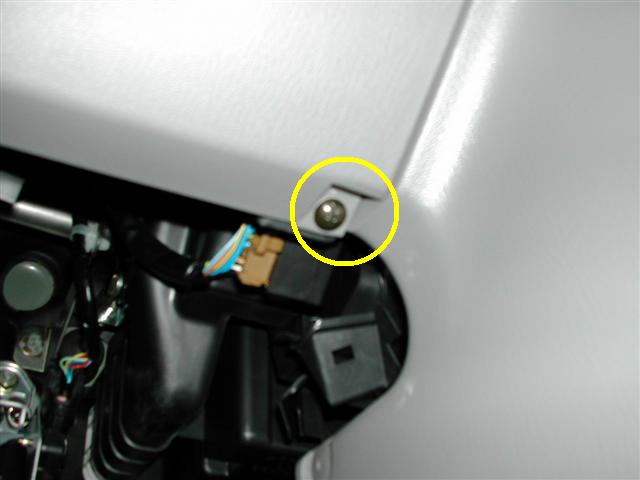
Step 2 - Remove the screw at
lower right of under-dash panel and carefully pop off the panel.
Three clips hold the panel across
the top and left side.
There's no need to disconnect any
wiring harnesses to any switches.
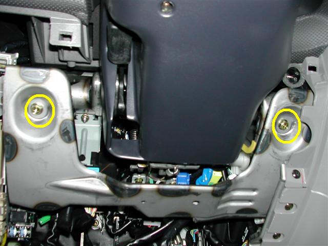
Step 3 - Remove the two screws
using a 10mm socket, and carefully remove the metal support bracket.
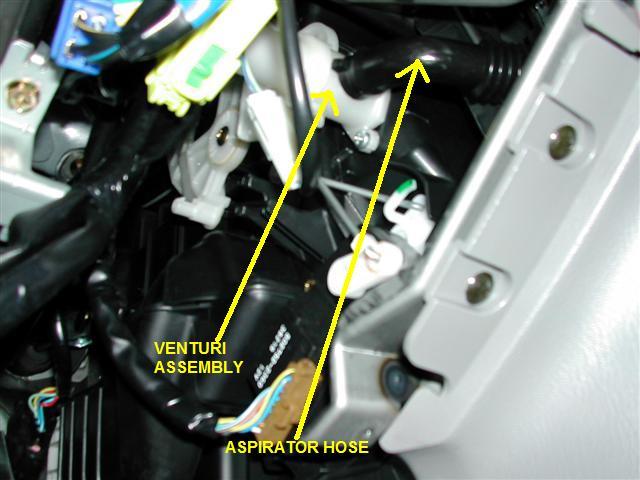
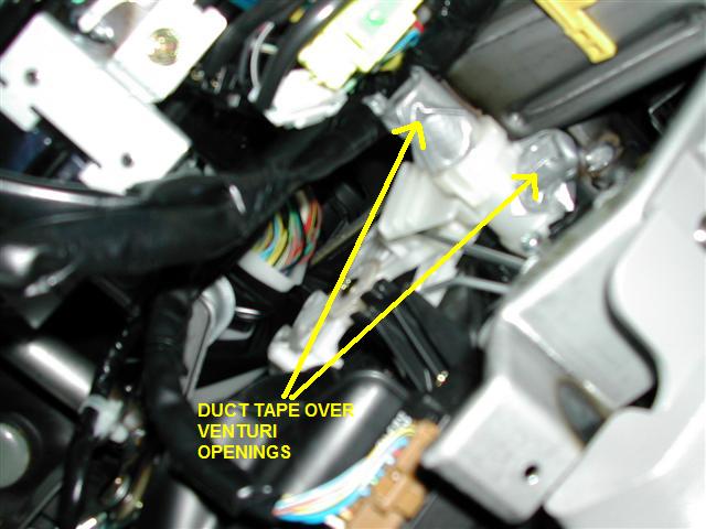
Step 4 - You will see the white Venturi
Assembly with the black Aspirator Hose attached.
Pull off the Aspirator Hose - it
comes off easily.
Step 5 - Duct Tape the two
Venturi openings - they are not needed any more.
As an added benefit, this will
also slightly increase the overall airflow from the system.
Step 6 - Attach the Aspirator
Hose to the CC-Fix Assembly. Don't use force - it will slide on
easily.
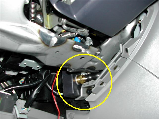
Step 7 - This is the tricky part.
Route the aspirator hose lower, install the metal support bracket.
Make sure that the hose is not
kinked or pinched. Place the assembly behind the metal bracket.
There is a small metal sleeve
that the box will fit into.
Make sure that it does not
interfere with the Vent Control Servo by turning the key to RUN, the fan to
HIGH,
and cycling through the Vent
Selector and Defroster.
All vents - dash, floor,
defroster - should work normally.
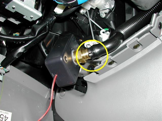
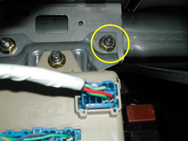
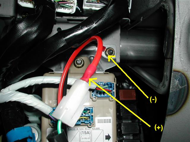
This is where you plug in the (+)
wire blade terminal. It is live only with ignition in RUN.
This is where you connect the (-)
Terminal. Use a 10mm socket to loosen and tighten nut.
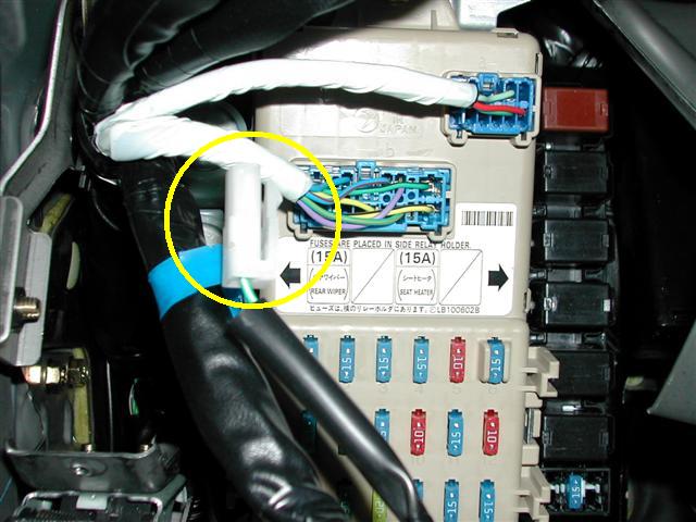
Step 8 - Make the final
connections.
Step 9 - Turn the key to Run,
make sure the CC-Fix fan is blowing air.
Hold a thread about 1/2 - 1/4
inch in front of the temperature sensor by the ignition key.
The thread should move towards
the sensor opening.
Assemble the under-dash panel
with 2 screws.
ENJOY the much improved Forester
Climate Control :)
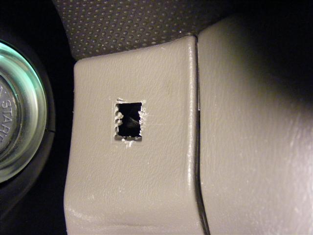
Additional steps you can take to further improve the system:
CAUTION! This involves cutting the dash sensor grill and is not reversible!
Snip and cut out the sensor grille slats. This further improves
airflow to the sensor and changes the air sampling bias from below dash
to dash level.
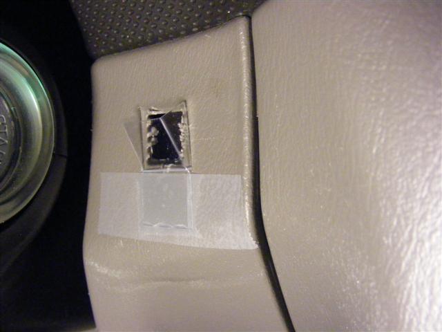
Fabricate
and attach a plastic air gate to change the air sampling bias towards
the upper dash. This will give the sensor a better reading of the
temperature the occupants are actually feeling.
I know this is not exactly pretty, but you can make it prettier and it's actually not very noticeable.