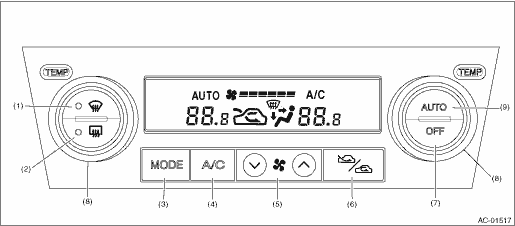
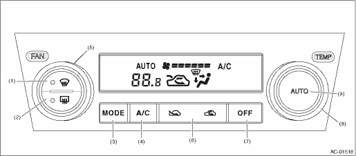
• DUAL AIR CONDITIONER MODEL
|
(1) |
Defroster switch |
(4) |
A/C switch |
(7) |
OFF switch |
|
(2) |
Rear window defogger switch |
(5) |
FAN switch |
(8) |
Temperature adjustment dial |
|
(3) |
Air flow control switch |
(6) |
FRESH/RECIRC switch |
(9) |
AUTO switch |
• SINGLE AIR CONDITIONER MODEL
NOTE:
For A/C system self-diagnosis, there is one that checks the control panel, and the other that checks the whole control system (sensor, actuator, blower motor, etc.). Perform the self-diagnosis for control panel first, and then perform the self-diagnosis for control system.
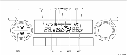
1. A/C CONTROL PANEL SELF-DIAGNOSIS

• DUAL AIR CONDITIONER MODEL
|
Switch |
Display screen |
Switch |
Display screen | ||
|
A/C switch |
(9) |
FAN switch (+) |
(6) | ||
|
AUTO switch |
(7) |
FAN switch (−) |
(5) | ||
|
Air flow control switch |
(10) |
Temperature control dial (right-hand dial) |
Driver’s side |
(3) | |
|
FRESH/RECIRC |
FRESH |
(8) |
Passenger’s side |
(16) | |
|
RECIRC |
(13) |
Temperature control dial (left-hand dial) |
Driver’s side |
(15) | |
|
Defroster switch |
(1) (2) |
Passenger’s side |
(11) | ||
|
Rear defogger switch |
(12) |
OFF switch |
(4) | ||
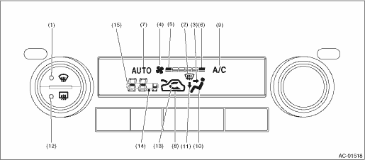
• SINGLE AIR CONDITIONER MODEL
|
Switch |
Display screen |
Switch |
Display screen | |
|
A/C switch |
(9) |
FAN switch (+) |
(6) | |
|
AUTO switch |
(7) |
FAN switch (−) |
(5) | |
|
Air flow control switch |
(10) |
Temperature control dial (right-hand dial) |
(14) | |
|
FRESH/RECIRC |
RECIRC: (8) |
Temperature control dial (left-hand dial) |
(15) | |
|
FRESH: (13) | ||||
|
Defroster switch |
(1) (2) |
OFF switch |
(4) | |
|
Rear defogger switch |
(12) |
|||
3. A/C CONTROL SYSTEM SELF-DIAGNOSIS
NOTE:
When the sunload sensor check is performed indoors or in the shade, it could be diagnosed as having an open circuit. Always check the sunload sensor with the sun shining on it.
|
Display screen (Malfunction at present) *1 |
Sensor |
Trouble contents |
|
21/AUTO Blink |
In-vehicle sensor |
Open |
|
−21/AUTO Blink |
Short | |
|
22/AUTO Blink |
Ambient sensor |
Sensor trouble or communication failure |
|
23/AUTO Blink |
Evaporator sensor |
Open |
|
−23/AUTO Blink |
Short | |
|
24/AUTO Blink |
Engine coolant temperature sensor |
Sensor trouble or communication failure |
|
25 Blink |
Sunload sensor |
Open *1 |
|
−25/AUTO Blink |
Short | |
|
26/AUTO Blink |
Air mix door actuator potentiometer (driver’s seat) |
COOL |
|
−26/AUTO Blink (Dual air conditioner only) |
Air mix door actuator potentiometer (passenger’s seat) |
COOL |
|
27/AUTO Blink |
Air mix door actuator potentiometer (driver’s seat) |
HOT |
|
−27/AUTO Blink (Dual air conditioner only) |
Air mix door actuator potentiometer (passenger’s seat) |
HOT |
|
28/AUTO Blink |
Mode door actuator potentiometer |
FACE |
|
29/AUTO Blink |
DEF | |
|
43/AUTO Blink (With rear vent only) |
Rear vent door actuator potentiometer |
OPEN |
|
44/AUTO Blink (With rear vent only) |
SHUT | |
|
20 Blink |
When all conditions are normal | |
*1: Present malfunction only is displayed for sunload sensor open circuit.
|
Display screen |
FRESH/RECIRC door |
Mode door |
Air mix door*1 |
Blower fan |
A/C compressor (Magnet clutch) |
Rear vent door open state*2 |
|
31 |
FRESH |
FACE |
Maximum cool |
LO |
OFF |
100% |
|
32 |
RECIRC |
FACE |
Maximum cool |
LO |
ON |
100% |
|
33 |
RECIRC |
FACE |
Maximum cool |
M1 |
ON |
100% |
|
34 |
FRESH |
B/L |
50% |
M1 |
ON |
100% |
|
35 |
FRESH |
FOOT |
50% |
M1 |
ON |
50% |
|
36 |
FRESH |
FOOT |
Maximum hot |
M3 |
ON |
50% |
|
37 |
FRESH |
F/D |
Maximum hot |
M3 |
ON |
50% |
|
38 |
FRESH |
DEF |
Maximum hot |
HI |
ON |
0% |
*1: In the dual air conditioner models, open states for driver’s side and passenger’s side are the same. *2: Models with rear vent only