|
PART
|
COLOR
|
LOCATION
|
DIAGRAM
|
|
12 VOLT CONSTANT
|
RED (+) and LIGHT GREEN/PURPLE (+)
|
@ IGNITION SWITCH HARNESS
|
|
|
STARTER
|
DARK GREEN (+)
|
@ IGNITION SWITCH HARNESS
|
|
|
STARTER 2
|
N/A
|
|
|
|
IGNITION 1
|
WHITE/YELLOW (+)
|
@ IGNITION SWITCH HARNESS
|
|
|
IGNITION 2
|
BLACK/LIGHT GREEN (+)
|
@ IGNITION SWITCH HARNESS
|
|
|
IGNITION 3
|
N/A
|
|
|
|
ACCESSORY/HEATER BLOWER 1
|
PURPLE/ORANGE (+)
|
@ IGNITION SWITCH HARNESS
|
|
|
ACCESSORY/HEATER BLOWER 2
|
N/A
|
|
|
|
KEYSENSE
|
N/A
|
|
|
|
PARKING LIGHTS ( - )
|
N/A
|
|
|
|
PARKING LIGHTS ( + )
|
See NOTE #2
|
See DIAGRAM
|
498_FREESTAR_FREESTAR WINDSTAR PARKING LIGHT DIAGRAM.pdf
|
|
POWER LOCK
|
WHITE/PURPLE (TYPE B)
|
@ SJB, BLACK 26 Pin Plug, Pin 3, See NOTE #3
|
|
|
POWER UNLOCK
|
DARK BLUE/LIGHT GREEN (TYPE B)
|
@ SJB, BLACK 26 Pin Plug, Pin 1, See NOTE #3
|
|
|
LOCK MOTOR WIRE
|
RED/ORANGE (+)
|
@ SJB, BLACK 5-Pin Plug, Pin 3, See NOTE #3
|
|
|
DOOR TRIGGER
|
ORANGE/WHITE (-)
|
@ SJB, GREY 26 Pin Plug, Pin 21, See NOTE #3
|
|
|
DOMELIGHT SUPERVISION
|
USE DOOR TRIGGER, (Requires Part #775 Relay)
|
|
|
|
TRUNK RELEASE
|
YELLOW (-)
|
@ SJB, GREY 26 Pin Plug, Pin 15, See NOTE #3
|
|
|
SLIDING POWER DOOR
|
N/A
|
|
|
|
HORN
|
DARK BLUE (-)
|
@ SJB, BLUE 52 Pin Plug, Pin 39, See NOTE #3
|
|
|
TACH
|
Any wire that is NOT RED (AC)
|
@ any IGNITON COIL or FUEL INJECTORS
|
|
|
WAIT TO START LIGHT
|
N/A
|
|
|
|
BRAKE
|
RED/LIGHT GREEN (+)
|
@ SJB, BLACK 36 Pin Plug, Pin 5, See NOTE #3
|
|
|
FACTORY ALARM DISARM
|
LIGHT BLUE/BLACK (-)
|
@ SJB, BLACK 26 Pin Plug, Pin 9, See NOTE #3
|
|
|
ANTI-THEFT
|
FORD'S ANTI-THEFT TRANSPONDER SYSTEM, SEE NOTE #1
|
@ IGNITION SWITCH TUMBLER
|
|
|
EXTRA INFORMATION
|

The (+) RED/LIGHT GREEN BRAKE wire is located in this BLACK Plug on the FRONT of the BCM/SJB in this vehicle.

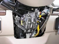
This PLASTIC UNDER DASH Panel must first be removed to gain access to the underdash wiring on this vehicle.
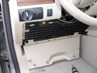
This is the second under dash panel that will need removed, this BLACK PLASTIC KNEE BOLSTER is held in place by (4) 8mm bolts.
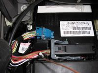
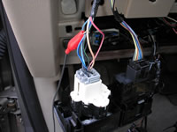
The BCM or SMB is part of the FUSEBOX under the DRIVERS SIDE of the DASH.

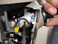
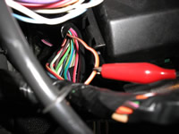
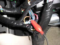
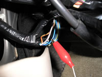
This shows the GRAY cover over top of the BLACK IGNITION SWITCH HARNESS Plug on this vheicle, the BLACK Plug can be removed form the IGNITION SWITCH Plug by removing the 8mm bolt that hold it into place in the middle of this plug.
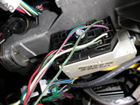
This shows the IGNITION SWITCH HARNESS Plug with the GRAY Cover removed, by doing this lets us see the wire colors on the IGNITION SWITCH Harness a little better.
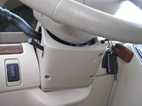
This shows the LOWER Steeing Column Cover that must be removed to gain access to the FACTORY TRANSPONDER System on this vehicle. You will need to remove the (3) Screws that hold this cover in place.
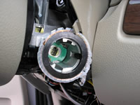
This view shows the LOWER STEERING COLUMN COVER removed, by doing this we can now see the TRANSPONDER System around the IGNITION SWITCH TUMBLER on this vehicle. NOTE ** this vehicle has the 791's TRANSPONDER LOOP ANTENNA already installed in this picture.
With the LOWER STEERING COLUMN COVER removed, you will next need to remove the IGNITION SWITCH TUMBLER by pressing in on the RELEASE PIN of the IGNITION SWITCH TUMBLER as shown in this picture.

By pressing in and turning on the IGNITION KEY at the same time, you can PULL OUT the IGNITION SWITCH TUMBLER from the Switch on the vehicle, you will need to do this so that you can remove the UPPER STEERING COLUMN COVER.
With the IGNITION SWITCH TUMBLER removed and the UPPER Steering Column Cover pull up and out of the way, you can now place the 791's TRANSPONDER LOOP ANTENNA around the FACTORY TRANSPONDER RECIEVER ANTENNA around the IGNITION SWITCH TUMBLER as seen in thi
This picture shows the (3) PARKING LIGHT wires at the BACK of the HEAD LIGHT Switch marked with the RED Clip, this switch removes from the dash by prying it out to gain access to the wires. This PARKING LIGHT System will requires (1) or (2) extra Relays P

The (-) DARK BLUE HORN wire can be found IN the AIRBAG HARNESS, under the DRIVERS DASH, when TESTING this wire, USE EXTREME CAUTION!!! it is the ONLY DARK BLUE wire in the AIR BAG HARNESS Plug.
The (-) ORANGE/WHITE DOOR TRIGGER/DOMELIGHT Supervision wire in located in the harness on the LEFT side of the BCM/SJB Module, heading under the dash in this picture and is marked with the RED Clip.
The (-) WHITE/PURPLE LOCK wire is marked with the RED Clip in this picture, the harness this wire is found in is the harness coming from the DRIVERS DOOR and heading towards the BCM/SJB Module.
The (-) DARKBLUE/LIGHT GREEN UNLOCK wire is marked with the RED Clip in this picture, the harness this wire is found in is the harness coming from the DRIVERS DOOR and heading towards the BCM/SJB Module.
|