
IMMOBILISER GT 165.2/3
CONNECTIONS
- Disconnect the negative terminal of the vehicle's battery prior to starting the installation.
- Mount the control unit in the passenger compartment, so as to provide access protection. Ensure that the unit and it's loom are mounted clear of high tension electronic interference, water spray and moving parts.
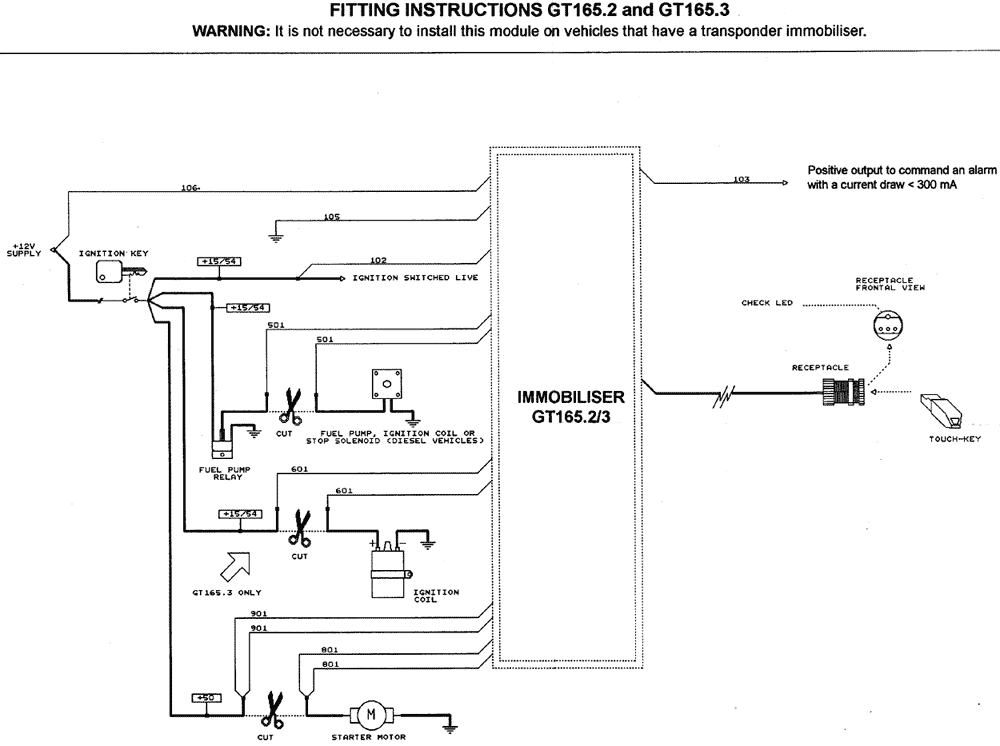
- Connect the 106 wire to a 12v supply wire.
- Connect the 105 wire to a negative (earth) point.
- The 102 wire is the ignition switched live (+ 15/54). Connect to a ignition switched live that remains live when the engine is cranked.
- Wire 103 provides a positive output when the system is armed (i. e. for an additional flashing GT75 LED). The maximum output current is 300 mA.
- Cut and remove a length (at least 300mm where possible) of the starter motor solenoid feed wire. Connect the 801 wires to one side of the cut and the 901 wires to the other.
- Cut and remove a length (at least 300mm where possible) of the fuel pump motor or engine stop solenoid feed wire. Connect a 501 wire to each cut end.
- The 601 wires, GT165. 3 only, immobilise another essential circuit i. e. ignition, glow plugs relay, engine management, fuel injection, crank position sensor, etc. Cut and remove a length (at least 300mm where possible) of one of these essential feeds. Connect a 601 wire to each cut end.
- Fit the receptacle to the dashboard, spare switch blank or steering column cowling, etc. Route and secure the receptacle wiring to the control unit an plug into the socket.
- Reconnect the vehicle battery. The system will immediately arm. Check system operation with both touch-keys.
SYSTEM OPERATION
Arming:
A few seconds after switching ignition off (passive arming period), engine immobilisations activate confirmed by the receptacle's check LED illuminating.
Disarming:
- Briefly press the touch-key into the receptacle. The check LED will extinguish.
- Switch the ignition on within the passive arming period.
When you turn the ignition off, after the passive arming period, you will obtain the arming of engine immobilisations and the automatic arming of any optional alarm connected to the 103 wire.
TECHNICAL DATA
| Input voltage: |
12VDC±4VDC. |
| Current draw: |
Control Unit < 5 mA. |
| Current draw: |
check led < 2 mA. |
| Immobiliser circuit capacity: |
501 wires = 15A @ 15VDC |
| |
601 wires, GT165. 3 only = 15A @ 15VDC
801 & 901 wires = 25A @ 15VDC |
| Operating temperature: |
-40° to+ 85° C. |
N. B. The manufacturer reserves the right to modify or improve the specification. The manufacturer cannot accept liability for any damage to the unit, or to the vehicle, due to incorrect installation. The product is covered by 12 month warranty from the date of the retail purchase
 1.07.2001