Alternator Overhaul
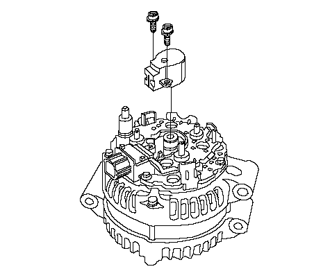
Exploded View
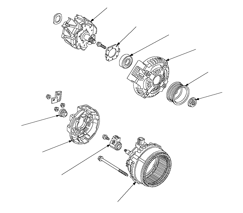 ROTORBEARING
RETAINERFRONT BEARINGDRIVE-END
HOUSINGPULLEYPULLEY
LOCKNUTTERMINAL
INSULATORBRUSH HOLDER
ASSEMBLYREAR HOUSING
ASSEMBLYEND COVERSpecial Tools Required
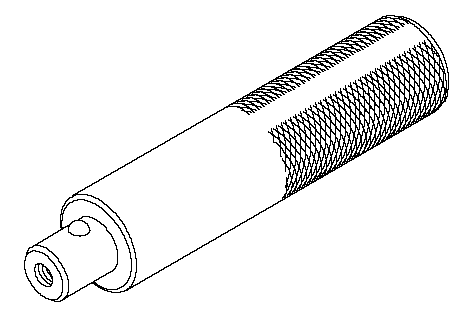
Handle driver ( 07749-0010000)
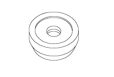
Driver attachment, 52 x 55 mm ( 07746-0010400)
NOTE: Refer to the Exploded View as needed during this procedure.
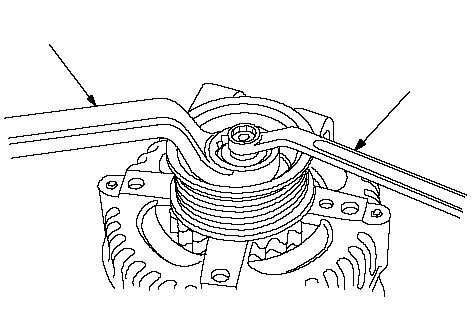
| 3. | If the front bearing needs replacing, remove the pulley locknut with a 10 mm wrench (A) and a 22 mm wrench (B). If necessary, use an impact wrench.
 BA BA |
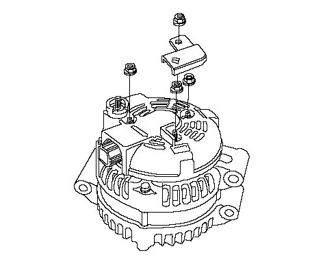
| 4. | Remove the harness stay and the three flange nuts from the alternator.
|
| 6. | Remove the brush holder.
|
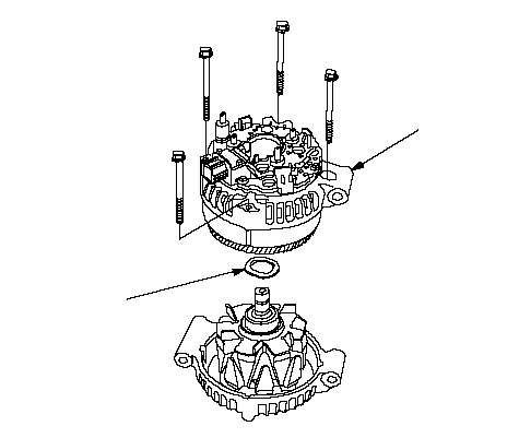
| 7. | Remove the four bolts, then remove the rear housing assembly (A), and washer (B).
 BA BA |
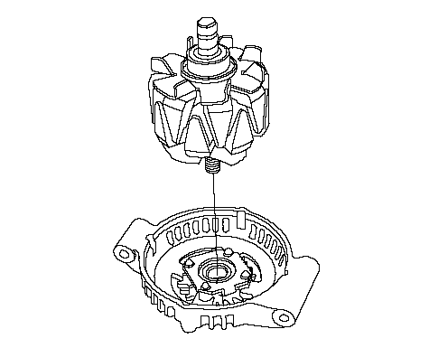
| 8. | If you are not replacing the front bearing, go to 13. Remove the rotor from the drive end housing.
|
| 9. | Inspect the rotor shaft for scoring, and inspect the bearing journal surface in the drive end housing for seizure marks.
- If the rotor is damaged, replace the rotor assembly.
- If the rotor is OK, go to 10.
|
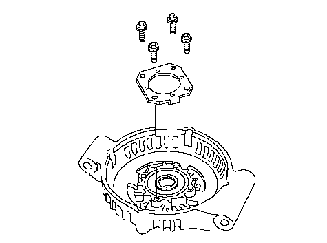
| 10. | Remove the front bearing retainer plate.
|
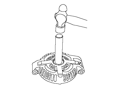
| 11. | Drive out the front bearing with a brass drift and hammer.
|
| 12. | With a hammer and special tools, install a new front bearing in the drive end housing.
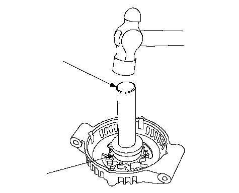 07749-001000007746-0010400 07749-001000007746-0010400 |
Alternator Brush Inspection
| 13. | Measure the length of both brushes (A) with vernier calipers (B).
- If either brush is shorter than the service limit,replace the brush holder assembly.
- If brush length is OK, go to 14.
Alternator Brush Length:| Standard (New): | 10.5 mm (0.41 in.) | | Service Limit: | 1.5 mm (0.06 in.) | 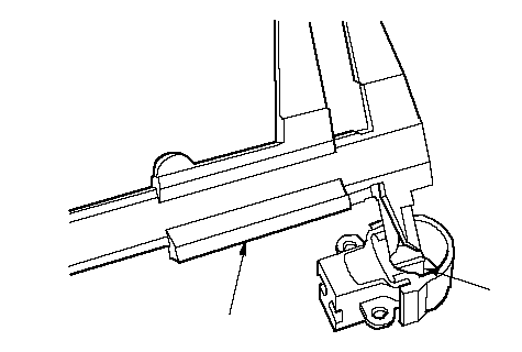 BA BA |
Rotor Slip Ring Test
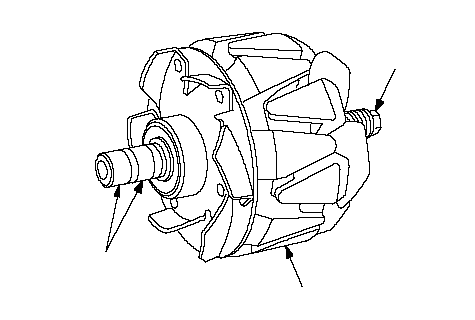
| 14. | Check that there is continuity between the slip rings (A).
- If there is continuity, go to 15.
- If there is no continuity, replace the rotor assembly.
 ABC ABC |
| 15. | Check that there is no continuity between each slip ring and the rotor (B) and the rotor shaft (C).
- If there is no continuity, replace the rear housing assembly, and go to 16.
- If there is continuity, replace the rotor assembly.
|
Alternator Reassembly
| 16. | If you removed the pulley, put the rotor in the drive-end housing, then tighten its locknut to 110 N·m (11.2 kgf·m, 81.0 lbf·ft).
|
| 17. | Remove any grease or any oil from the slip rings.
|
| 18. | Put the rear housing assembly and drive-end housing/rotor assembly together, tighten the four through bolts.
|
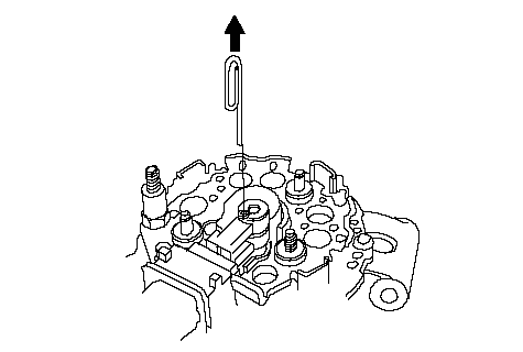
| 19. | Push the brushes (A) in, then insert a pin or drill bit (B) (about 1.6 mm (0.06 in.) diameter) to hold them there.
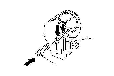 BA BA
|
| 20. | Install the brush holder, and pull out the pin.
|
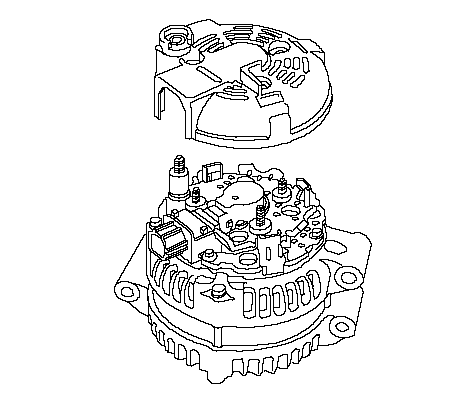
| 21. | Install the end cover.
|
| 22. | After assembling the alternator, turn the pulley by hand to make sure the rotor rotates smoothly and without noise.
|