SRS Indicator Circuit Troubleshooting
SRS Indicator Circuit Troubleshooting
The SRS Indicator Doesn't Come On
| 1. | Turn the ignition switch ON (II), and see if the other indicators come on (brake system, etc). Do the other indicators come on? YES - Go to 2. NO - Go to 8. |
| 2. | Turn the ignition switch OFF, then remove the gauge assembly. Disconnect the gauge assembly connector (30P) (A) from the gauge assembly.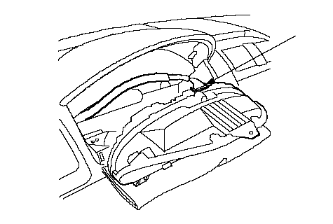 A A |
| 3. | Check resistance between the No. 21 terminal of gauge assembly connector (30P) and body ground. There should be 0-1.0 W.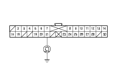 GAUGE ASSEMBLY CONNECTOR (30P)Wire side of female terminalsBLK GAUGE ASSEMBLY CONNECTOR (30P)Wire side of female terminalsBLKIs the resistance as specified? YES - Go to 4. NO - Open in the BLK wire of the dashboard wire harness, junction connector or faulty body ground terminal (G501 or G503). If the body ground terminal is OK, replace the dashboard wire harness.n |
| 4. | Check for voltage between the No. 14 terminal of gauge assembly connector (30P) and body ground within the first 6 seconds after turning the ignition switch ON (II). There should be about 1.0 V for 6 seconds and then about 11 V.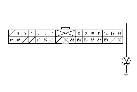 GAUGE ASSEMBLY CONNECTOR (30P)Wire side of female terminalsPNK GAUGE ASSEMBLY CONNECTOR (30P)Wire side of female terminalsPNKIs the voltage as specified? YES - Go to 5. NO - Faulty SRS indicator circuit in the gauge assembly; replace the gauge assembly.n |
| 5. | Turn the ignition switch OFF. |
| 6. | Disconnect SRS unit connector A (28P) from the SRS unit.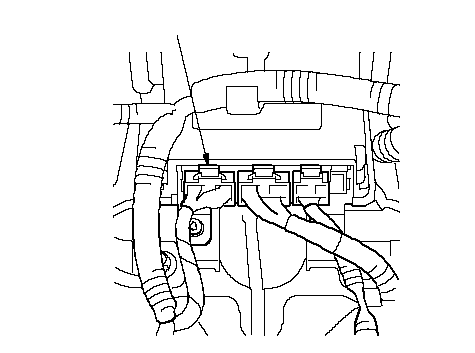 A A |
| 7. | Connect a voltmeter between the No. 14 terminal of the gauge assembly connector (30P) and body ground. Turn the ignition switch ON (II), and measure voltage. There should be 0.5 V or less.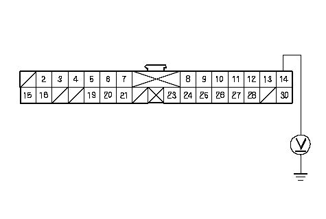 GAUGE ASSEMBLY CONNECTOR (30P)Wire side of female terminalsPNK GAUGE ASSEMBLY CONNECTOR (30P)Wire side of female terminalsPNKIs the voltage as specified? YES - Faulty SRS unit; replace the SRS unit.n NO - Short to power in the PNK wire of the dashboard wire harness or junction connector; replace the dashboard wire harness.n |
| 8. | Turn the ignition switch OFF. Check the No. 21 ( 7.5A) fuse in the under-dash fuse/relay box. Is the fuse blown? YES - Go to 10. NO - Go to 9. |
| 9. | Connect a voltmeter between the No. 5 terminal of the gauge assembly connector (30P) and body ground. Turn the ignition switch ON (II), and measure the voltage. There should be battery voltage.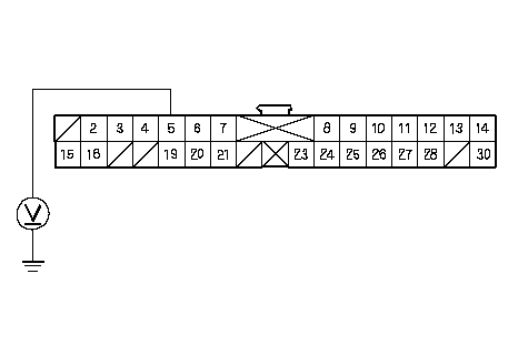 GAUGE ASSEMBLY CONNECTOR (30P)Wire side of female terminalsYEL GAUGE ASSEMBLY CONNECTOR (30P)Wire side of female terminalsYELIs there battery voltage? YES - Faulty SRS indicator circuit in the gauge assembly or poor contact at the gauge assembly connector (30P) and gauge assembly; if the connection is OK, replace the gauge assembly.n NO - Open in the under-dash fuse/relay box No. 21 (7.5A) fuse circuit, or open in the YEL wire of the dashboard wire harness, junction connector. If the under-dash fuse/relay box is OK, replace the dashboard wire harness.n |
| 10. | Replace the No. 21 (7.5A) fuse, and check to see if the SRS indicator comes on. Do the SRS indicator come on? YES - The system is OK at this time.n NO - Repair the short to ground in the under-dash fuse/relay box No. 21 (7.5A) fuse circuit.n |
The SRS Indicator Stays On
| 1. | Turn the ignition switch OFF. Disconnect the battery negative cable, and wait for 3 minutes. |
| 2. | Disconnect SRS unit connector A (28P) from the SRS unit.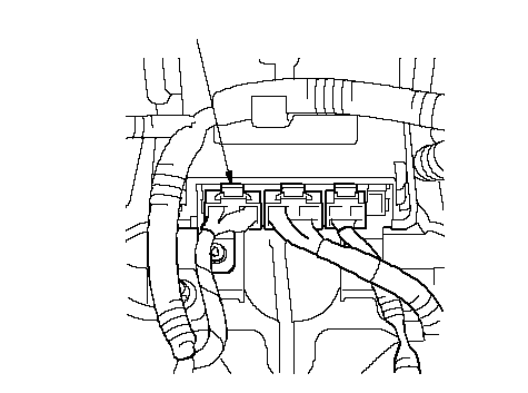 A A |
| 3. | Remove the gauge assembly. Disconnect the gauge assembly connector (30P) (A) from the gauge assembly.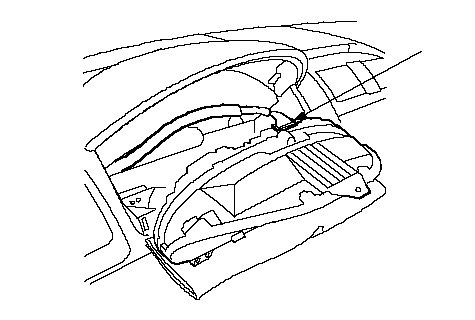 A A |
| 4. | Check resistance between the No. 14 terminal of gauge assembly connector (30P) and the No. 19 terminal of SRS unit connector A (28P). Tere shoud be 1 W or less.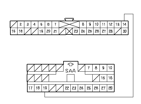 GAUGE ASSEMBLY CONNECTOR (30P)Wire side of female terminalsPNKPNKSRS UNIT CONNECTOR A (28P) GAUGE ASSEMBLY CONNECTOR (30P)Wire side of female terminalsPNKPNKSRS UNIT CONNECTOR A (28P)Is the resistance as specified? YES - Faulty SRS indicator circuit in the gauge assembly or poor contact at gauge assembly connector (30P); check the connection. If the connection is OK, replace the gauge assembly.n NO - Open in the dashboard wire harness; replace the dashboard wire harness.n |