M/T Countershaft Reassembly (M/T)
M/T Countershaft Reassembly
Exploded View
5-speed model:
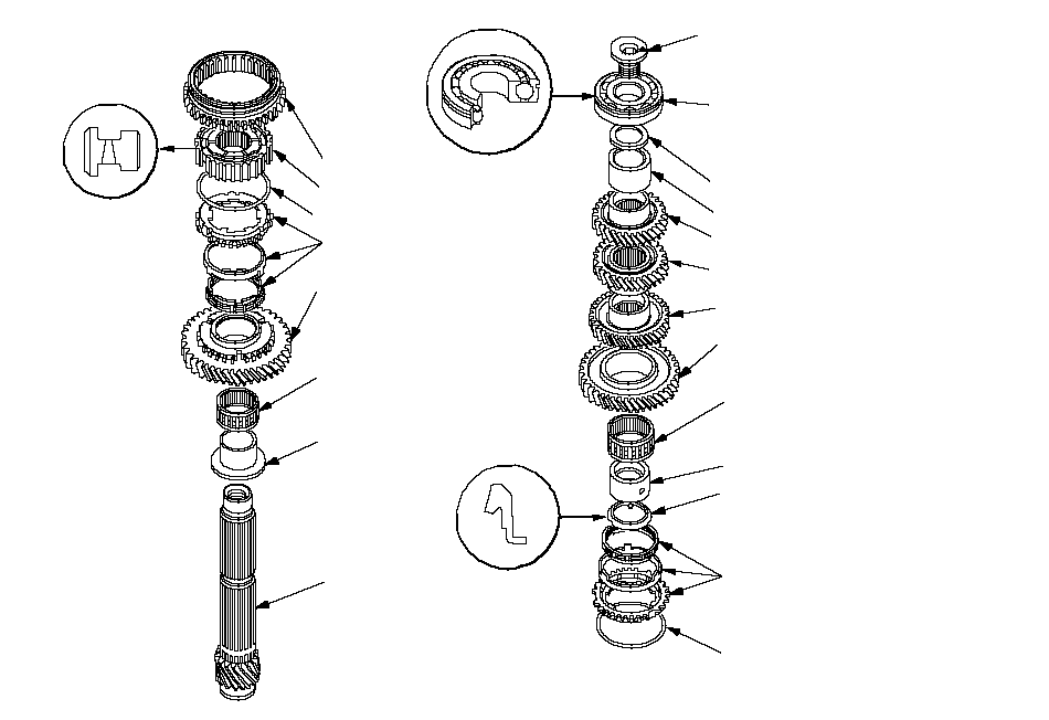 2ND GEARDISTANCE COLLARSYNCHRO SPRINGREVERSE GEAR1ST/2ND SYNCHRO HUBFRICTION DAMPER
Check for wear and damage.SYNCHRO SPRING1ST GEARCOUNTERSHAFT3RD GEARNEEDLE BEARING
Check for wear
and operation.4TH GEAR5TH GEARBALL BEARING
Check for wear and
operation.
Note the direction of installation.NEEDLE BEARING
Check for wear and
operation.TRIPLE CONE SYNCHRODISTANCE COLLARSPECIAL BOLT
Replace.
118 N·m (12 kgf·m, 87 lbf·ft)35 mm SHIMDISTANCE COLLARTRIPLE CONE SYNCHRO
6-speed model:
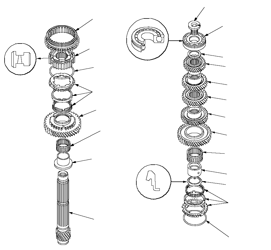 SYNCHRO SPRING1ST GEARCOUNTERSHAFTBALL BEARING
Check for wear
and operation.
Note the direction
of installation.2ND GEARFRICTION DAMPER
Check for wear
and damage.SYNCHRO SPRING1ST/2ND
SYNCHRO HUBREVERSE GEARNEEDLE BEARING
Check for wear and
operation.NEEDLE BEARING
Check for wear and
operation.4TH GEAR5TH GEAR3RD GEARDISTANCE COLLARTRIPLE CONE SYNCHRODISTANCE COLLARTRIPLE CONE
SYNCHROSPECIAL BOLT
Replace.
118 N·m (12 kgf·m, 87 lbf·ft)6TH GEAR35 mm SHIM
Special Tools Required
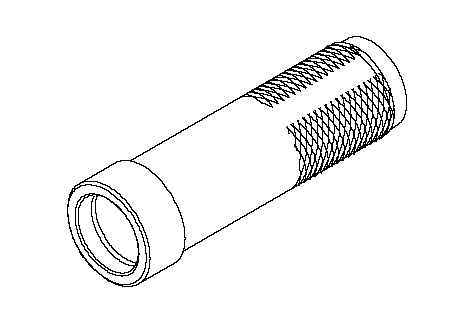
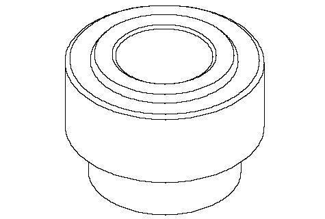
Driver, 40 mm I.D. ( 07746-0030100)
NOTE:
- Refer to the Exploded View as needed during this procedure.
- 6-speed model is shown, 5-speed model is similar.
| 1. | Clean all parts in solvent, dry them, and apply lubricant to all contact surfaces. |
| 2. | Install the distance collar and needle bearing onto the countershaft. |
| 3. | Install the triple cone synchro assembly (A) by aligning the synchro cone fingers (B) with 1st gear grooves (C), then install the synchro spring (D).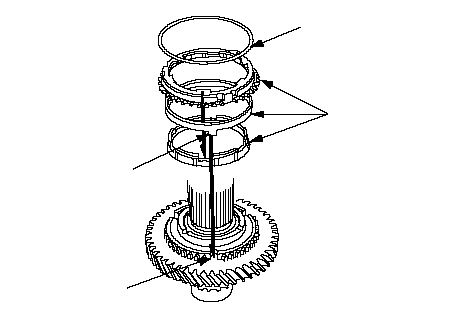 DABC DABC |
| 4. | Install the 1st/2nd synchro hub (A) by aligning the synchro cone fingers (B) with the 1st/ 2nd synchro hub grooves (C).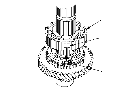 ACB ACB |
| 5. | Install the reverse gear. |
| 6. | Install the synchro spring (A).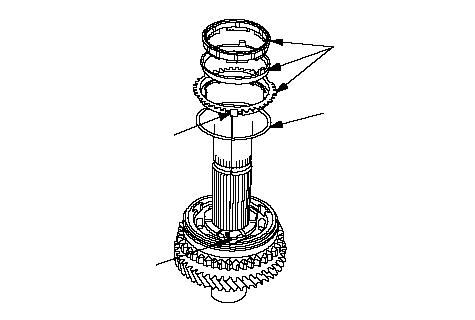 BACD BACD |
| 7. | Install the triple cone synchro assembly (B) by aligning the synchro cone fingers (C) with the 1st/2nd synchro hub grooves (D). |
| 8. | Install the distance collar (A) and friction damper (B) by aligning the friction damper fingers (C) with the 1st/2nd synchro hub grooves (D).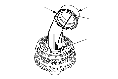 ACBD ACBD |
| 9. | Install the needle bearing. |
| 10. | Install the 2nd gear (A) by aligning the synchro cone fingers (B) with the 2nd gear grooves (C).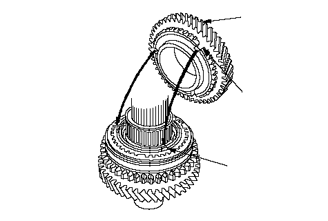 ACB ACB |
| 11. | Support the countershaft (A) on the steel blocks, then install 3rd gear (B) using the special tool and a press (C). Do not exceed the maximum pressure.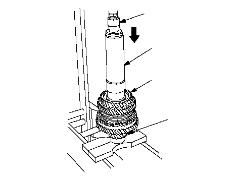 BA07746-0030100C BA07746-0030100C14,700 N (1,500 kgf, 3,307 lbf) max. |
| 12. | Install the 4th gear (A) using the special tool and a press (B). Do not exceed the maximum pressure.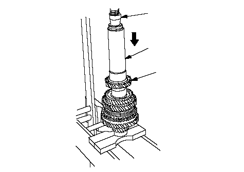 B B14,700 N (1,500 kgf, 3,307 lbf) max.A07746-0030100 |
| 13. | Install the 5th gear (A) using the special tool and a press (B). Do not exceed the maximum pressure.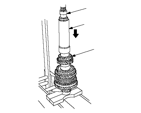 B B14,700 N (1,500 kgf, 3,307 lbf) max.A07746-0030100 |
| 14. | Install the distance collar (5-speed model). |
| 15. | Install 6th gear (A) using a special tools and a press (B). Do not exceed the maximum pressure.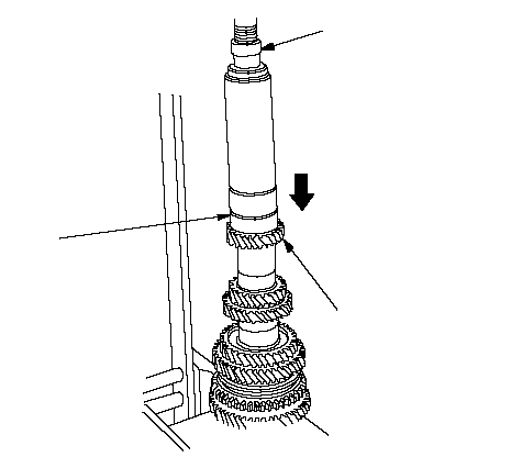 AB AB14,700 N (1,500 kgf, 3,307 lbf) max.07746-0030300 |
| 16. | Install the 35 mm shim and the old ball bearing (A) using a special tools and a press (B).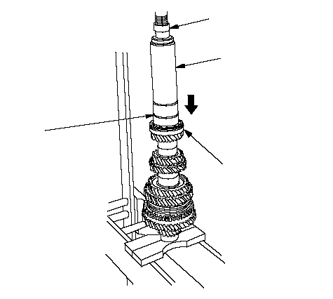 A07746-0030300B07746-0030100 A07746-0030300B07746-0030100 |
| 17. | Measure the clearance between the old bearing (A) and the 35 mm shim (B) with a feeler gauge (C).
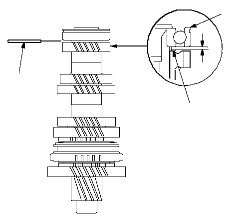 CAB CAB |
| 18. | If the clearance is more than the standard, select a new shim from the following table. If the clearance measured in step 17 is within the standard, replace only the new ball bearing.
|
| 19. | Support ball bearing (A) (5-speed model) or 6th gear (B) (6-speed model) on steel blocks (C), then use a press (D) and an attachment (E) to press the countershaft out of the ball bearing.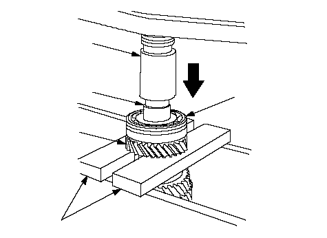 DEACB DEACB |
| 20. | If necessary, install the 35 mm shim selected in step 18, then recheck the clearance. |
| 21. | Install 6th gear (A) using a special tools and a press (B). Do not exceed the maximum pressure.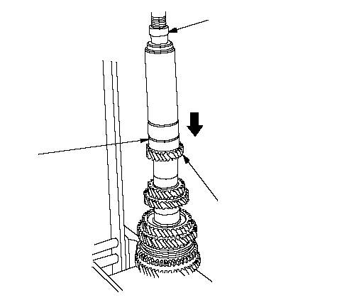 AB AB14,700 N (1,500 kgf, 3,307 lbf) max.07746-0030300 |
| 22. | Install the new ball bearing (A) using a special tools and a press (B).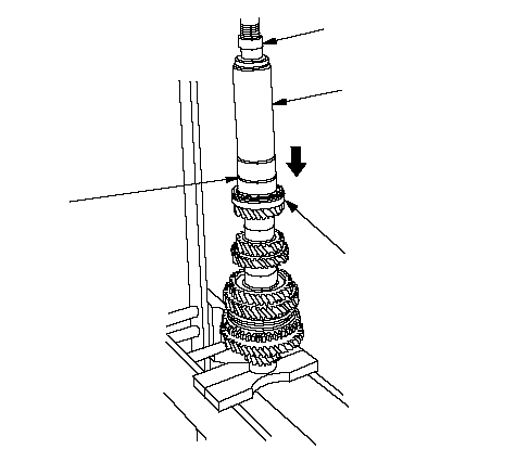 A07746-0030300B07746-0030100 A07746-0030300B07746-0030100 |
| 23. | Tighten the new special bolt (A) (left-hand threads).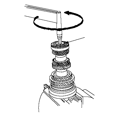 A A118 N·m (12 kgf·m, 87 lbf·ft) |