A/T Clutch Clearance Inspection (A/T)
A/T Clutch Clearance Inspection
Special Tools Required
Clutch compressor attachment ( 07ZAE-PRP0100)
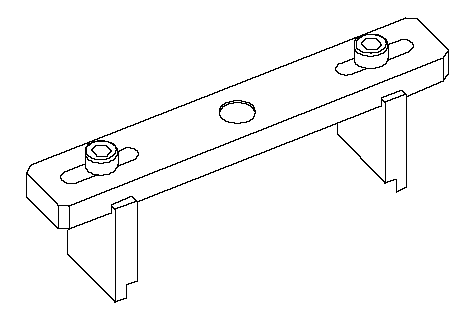
| 1. | Inspect the clutch piston, discs, plates, and end plate for wear and damage, and inspect clutch waved-plate phase difference, if necessary. |
| 2. | Install the clutch piston in the clutch drum. Do not install the O-rings during inspection.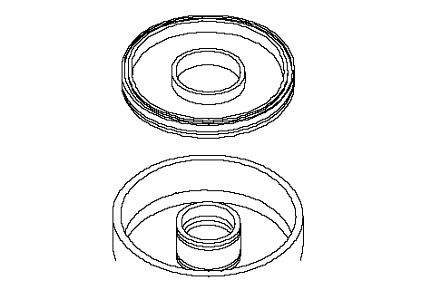 |
| 3. | For K20A6 Engine model 1st Clutch: Install the waved spring (A) in the clutch drum (B). Starting with the clutch waved-plate, alternately install the clutch waved-plates (C) (4), and discs (D) (4), and install the clutch-end-plate (E) with the flat side toward the disc. 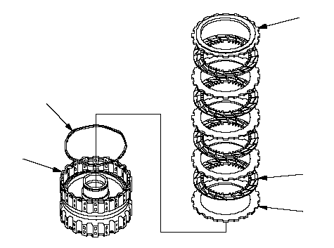 CBDAE CBDAE |
| 4. | For K20A6 Engine model 2nd Clutch: Install the waved spring (A) in the clutch drum (B). Install the clutch flat-plate (C), and clutch disc (D). Starting with the clutch waved-plate, alternately install the clutch waved-plates (E) (3), and discs (F) (3), and install the clutch-end-plate (G) with the flat side toward the disc. 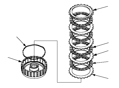 BCDAGFE BCDAGFE |
| 5. | For K20A6 Engine model 3rd Clutch: Install the waved spring (A) in the clutch drum (B). Install the clutch flat-plate (C), and clutch disc (D). Starting with the clutch waved-plate, alternately install the clutch waved-plates (E) (3), and discs (F) (3), and install the clutch-end-plate (G) with the flat side toward the disc. 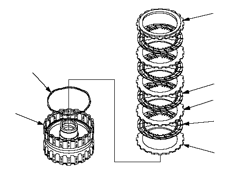 BCDAFEE BCDAFEE |
| 6. | For K20A6 Engine model 4th Clutch: Install the waved spring (A) in the clutch drum (B). Starting with the clutch waved-plate, alternately install the clutch waved-plates (C) (3), and discs (D) (3), and install the clutch-end-plate (E) with the flat side toward the disc. 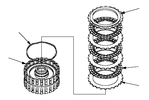 CADBE CADBE |
| 7. | For K20A6 Engine model 5th Clutch: Install the waved spring (A) in the clutch drum (B). Starting with the clutch waved-plate, alternately install the clutch waved-plates (C) (3), and discs (D) (3), and install the clutch-end-plate (E) with the flat side toward the disc. 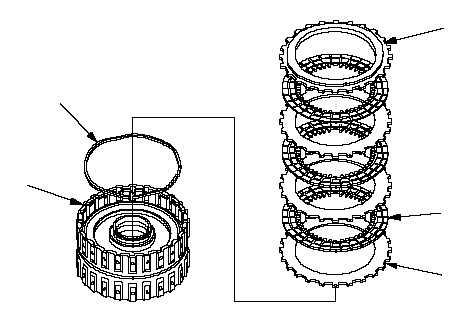 CADBE CADBE |
| 8. | For K24A3 Engine model 1st Clutch: Install the waved spring (A) in the clutch drum (B). Starting with the clutch plate, alternately install the clutch plate (C) (5) and discs (D) (5), then install the clutch-end-plate (E) with the flat side toward the disc. 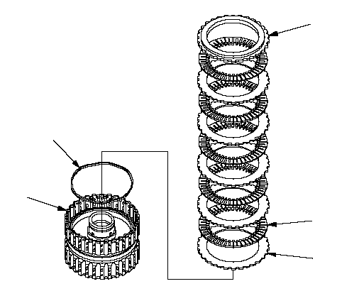 CBDAE CBDAE |
| 9. | For K24A3 Engine model 2nd Clutch: Install the waved spring (A) in the clutch drum (B). Install the 4.0 mm-thick plate (C) with the sheer droop side (D) toward the inside of the drum, clutch disc (E), and 2.0 mm-thick flat-plate (F), then starting with the disc, alternately install the discs (G) (4) and waved-plates (H) (3), then install the clutch-end-plate (I) with the flat side toward the disc. 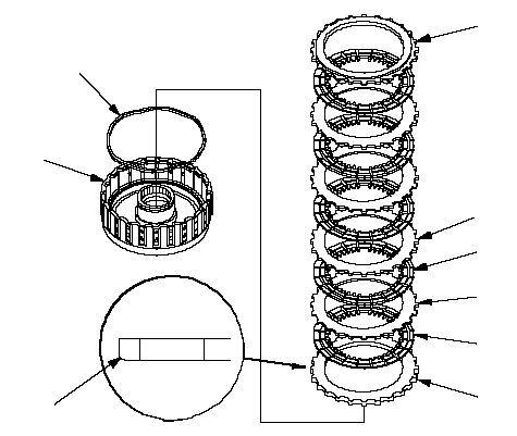 ECFABHGID ECFABHGID |
| 10. | For K24A3 Engine model 3rd Clutch: Install the waved spring (A) in the clutch drum (B). Starting with the clutch plate, alternately install the clutch plate (C) (5) and discs (D) (5), then install the clutch-end-plate (E) with the flat side toward the disc. 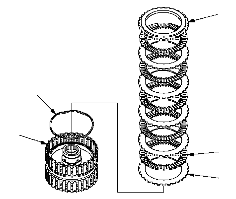 CBDAE CBDAE |
| 11. | For K24A3 Engine model 4th Clutch: Install the waved spring (A) in the clutch drum (B). Starting with the clutch waved-plate, alternately install the clutch plates (C) (4) and discs (D) (4), then install the clutch-end-plate (E) with the flat side toward the disc. 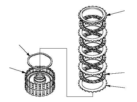 CBDAE CBDAE |
| 12. | For K24A3 Engine model 5th Clutch: Install the waved spring (A) in the clutch drum (B). Starting with the clutch waved-plate, alternately install the clutch plates (C) (4) and discs (D) (4), then install the clutch-end-plate (E) with the flat side toward the disc. 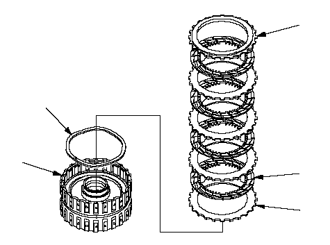 CBDAE CBDAE |
| 13. | Install the snap ring with a screwdriver.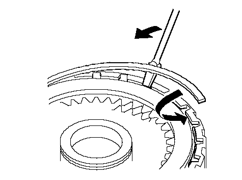 |
| 14. | Set a dial indicator (A) on the clutch end plate (B).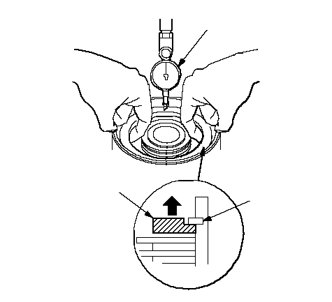 ACB ACB |
| 15. | Zero the dial indicator with the clutch end plate lifted up to the snap ring (C). |
| 16. | Release the clutch end plate to lower the clutch end plate, then put the special tool on the end plate (A).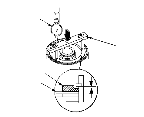 BADC07ZAE-PRP0100 BADC07ZAE-PRP0100 |
| 17. | Except for K24A3 engine model 1st and 3rd clutches: Press the special tool down with 150-160 N (15-16 kgf, 33-35 lbf) using a force gauge, and read the dial indicator (B). |
| 18. | For K24A3 engine model 1st and 3rd clutches: Press the special tool down with 39 N (4.0 kgf, 9 lbf) using a force gauge, and read the dial indicator (B). |
| 19. | The dial indicator reads the clearance (C) between the clutch end plate and top disc (D). Take measurements in at least three places, and use average as the actual clearance.
| ||||||||||||||||||||||||||||
| 20. | If the clearance is out of the service limit, select a new clutch end plate from the following table.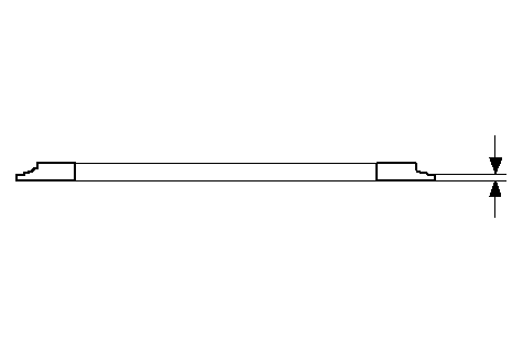
|
| 21. | Install the new clutch end plate, then recheck the clearance. |
| 22. | If the thickest clutch end plate is installed, but the clearance is still over the service limit, replace the clutch discs and plates. |