Power Steering Pump Overhaul
Exploded View
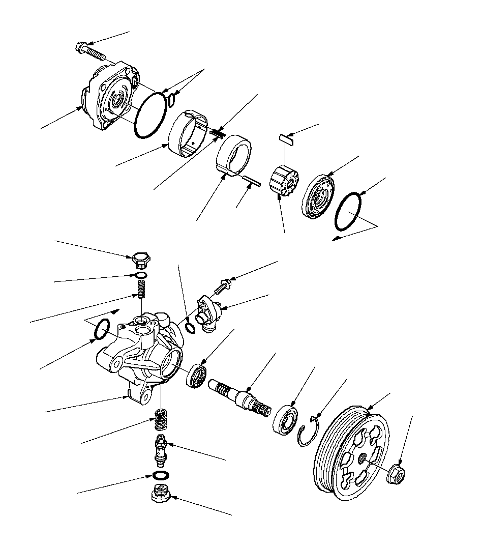 PRESSURE CONTROL VALVE CAP
49 N·m (5.0 kgf·m, 36 lbf·ft)PULLEY NUT
64 N·m
(6.5 kgf·m,
47 lbf·ft)*CAM RINGVANES
(11 plates)*SIDE PLATE23.8 x 2.4 mm O-RING
Replace.16.7 x 1.8 mm O-RING
Replace.PRESSURE CONTROL
VALVE*ROTORPUMP COVER SEALS
Replace.*DRIVE SHAFTBALL BEARING40 mm SNAP RINGPULLEYReplace the pump as an assembly if the parts indicated with asterisk (*) are worn or damaged.INLET JOINT6 x 1.0 mm
11 N·m
(1.1 kgf·m, 8 lbf·ft)PRESSURE CONTROL
VALVE SPRING*OUTER CASESLIPPER SEAL
(White color)
Replace.RUBBER SEAL
(Black color)
Replace.*ROLL PIN*PUMP COVER8 x 1.25 mm
20 N·m
(2.0 kgf·m, 14 lbf·ft)13 x 1.9 mm O-RING
Replace.PUMP SEAL
Replace.PUMP HOUSING CAP
29 N·m
(3.0 kgf·m, 22 lbf·ft)12.7 x 1.8 mm O-RING
Replace.PUMP PRELOAD
SPRING51 x 2.4 mm O-RING
Replace.PUMP HOUSING******Special Tools Required
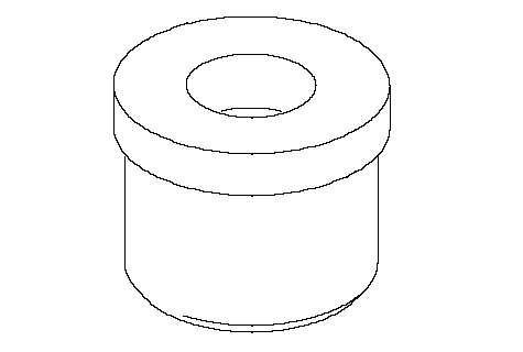
Attachment, 32 x 35 mm ( 07746-0010100)
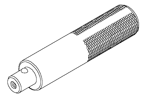
Driver ( 07749-0010000)
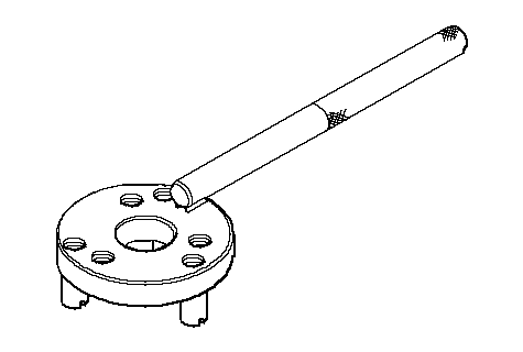
Pulley holder ( 07ZAB-S5A0100)
Disassembly
NOTE: Refer to the Exploded View as needed during the following procedure.
| 2. | Drain the fluid from the pump.
|
| 3. | Hold the steering pump (A) a vise with soft jaws (B), hold the pulley (C) with the special tool (D), and remove the pulley nut (E) and pulley. Be careful not to damage the pump housing with the jaws of the vise.
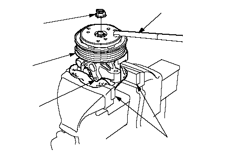 D D
07ZAB-S5A0100ECAB |
| 4. | Remove the inlet joint and O-ring.
|
| 5. | Remove the pressure control valve cap, O-ring, valve spring, and pressure control valve.
|
| 6. | Remove the pump housing cap, O-ring, and pump preload spring.
|
| 7. | Remove the pump cover and pump cover seals.
|
| 9. | Remove the outer case, cam ring, rotor, vanes, and side plate.
|
| 10. | Remove the rubber seal and slipper seal from the outer case.
|
| 11. | Remove the O-rings from the bottom of the housing.
|
| 12. | Remove the snap ring, then remove the drive shaft by tapping the shaft end with the plastic hammer.
|
| 13. | Remove the seal from the pump housing.
|
Inspection
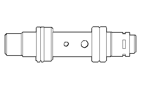
| 14. | Check the pressure control valve for wear, burrs, and other damage to the edges of the grooves in the valve.
|
| 15. | Inspect the bore of the pressure control valve on the pump housing for scratches and wear.
|
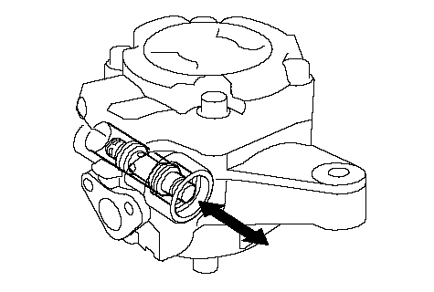
| 16. | Slip the pressure control valve back in the pump housing, and check that it moves in and out smoothly. If OK, go to 17; if not, replace the pump as an assembly. The pressure control valve is not available separately.
|
| 17. | Attach a hose (A) to the end of the pressure control valve (B) as shown. Then submerge the pressure control valve in a container of power steering fluid or solvent (C), and blow in the hose.
- If air bubbles leak through the valve at less than 98 kPa (1.0 kgf/cm2, 14.2 psi), replace the pump as an assembly. The pressure control valve is not available separately.
- If the pressure control valve is OK, set it aside for reassembly later.
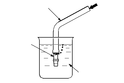 ACB ACB |
| 18. | Inspect the ball bearing by rotating the outer race slowly. If you feel any play (axial or radial) or roughness, remove the faulty ball bearing (A), and install a new one (B).
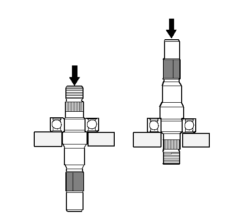 AB AB |
| 19. | Inspect each part shown with an asterisk in the Exploded View; if any of them are worn or damaged, replace the pump as an assembly.
|
Reassembly
| 20. | Install the new pump seal (A) (with its grooved side facing in) into the pump housing (B) by hand first, then drive it in using the special tools with until there is no step at the top of the pump seal, and the seal is fully seated in the pump housing.
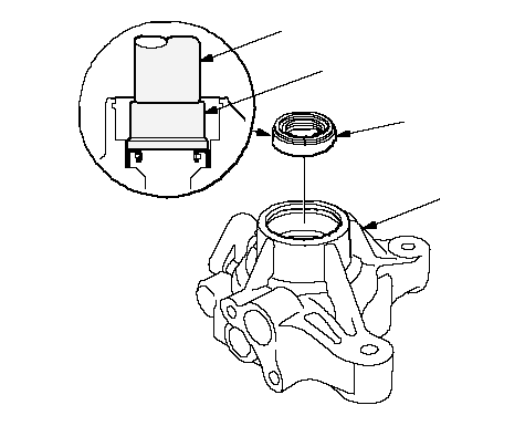 07749-001000007746-0010100AB 07749-001000007746-0010100AB |
| 21. | Position the pump drive shaft (A) in the pump housing, then press it in with the appropriate size socket wrench (B) as shown. Do not apply more than 1,370 N (140 kgf, 308 lbf) of pressure.
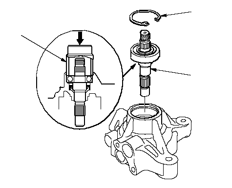 CAB CAB |
| 22. | Install the 40 mm snap ring (C) with its radiused edge facing out.
|
| 23. | Coat the new 23.8 mm O-ring (A) with the power steering fluid, then position it on the bottom (B) of the pump housing.
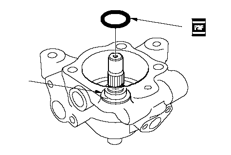 AB AB |
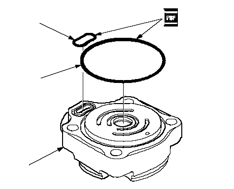
| 24. | Coat the new cover seals (A) and (B) with the power steering fluid, then position them into the grooves on the cover (C).
 BAC BAC |
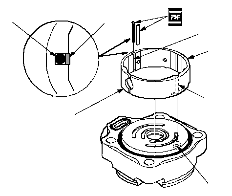
| 25. | Install the outer case (A) by aligning the slot (B) inside the outer case with the cover roll pin hole (C). Be sure that the slit (D) on the outer case is to direction shown.
 FABCDEG FABCDEG |
| 26. | Apply the power steering fluid to the rubber seal (E) (black), and install it in the slot (F) of the outer case.
|
| 27. | Apply power steering fluid to the slipper seal (G) (white), and install it on top of the rubber seal you just installed.
|
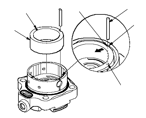
| 28. | Install the cam ring (A) with the ‘‘·'' mark (B) facing up. Align the slot (C) with the slot (D) in the outer case.
 EDFCBA EDFCBA |
| 29. | Insert the roll pin (E) into the slots between the cam ring and outer case, then push roll pin into the set hole (F).
|
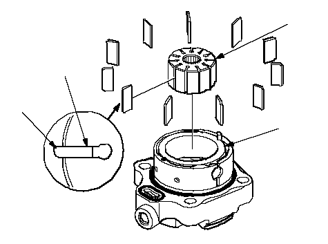
| 30. | Install the rotor (A) in the cam ring (B).
 ABCD ABCD |
| 31. | Set the 11 vanes (C) in the grooves in the rotor. Make sure that the round ends (D) of the vanes are in contact with the sliding surface of the cam ring.
|
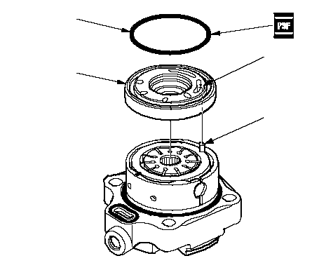
| 32. | Place the side plate (A) on the cam ring, and aligning the roll pin set hole (B) in the side plate with the roll pin end (C).
 BCDA BCDA |
| 33. | Coat the new O-ring (D) with the power steering fluid, then position it into the groove on the side plate.
|
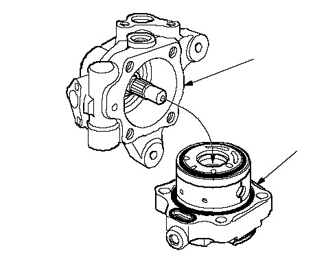
| 34. | Install the pump housing (A) over the cover assembly (B).
 AB AB |
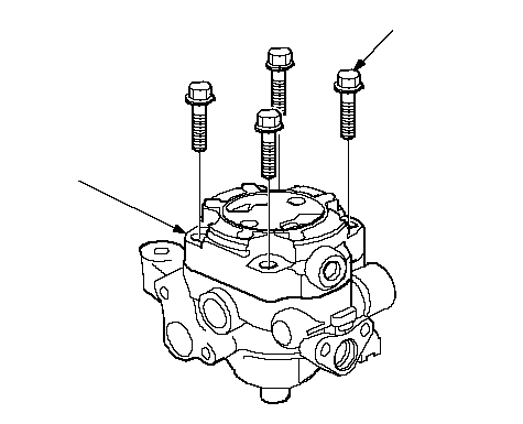
| 35. | Align the bolt holes in the cover (A) with the threaded holes in the pump housing. Install the flange bolts loosely first, then torque the flange bolts in a criss cross pattern in two or more steps.
 8 x 1.25 mm 8 x 1.25 mm
20 N·m
(2.0 kgf·m,
14 lbf·ft)A |
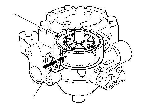
| 36. | Push in the cam ring (A) from the pump housing cap hole (B) with a flat blade screwdriver, to make sure the cam ring is fully seated against the outer case.
 AB AB |
| 37. | Install the pump preload spring (A) in the pump housing.
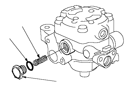 C C
29 N·m (3.0 kgf·m, 22 lbf·ft)BA |
| 38. | Coat the new 12.7 mm O-ring (B) with power steering fluid, and install it on the pump housing cap (C).
|
| 39. | Install the pump housing cap on the pump housing, and tighten it to specified torque.
|
| 40. | Install the pressure control valve spring (A) in the pump housing.
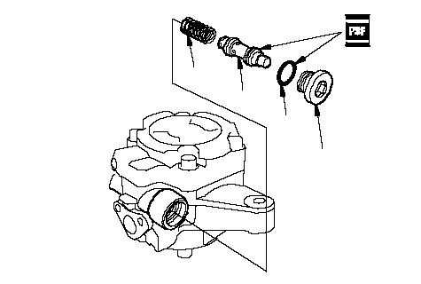 D D
49 N·m
(5.0 kgf·m,
36 lbf·ft)BAC |
| 41. | Coat the pressure control valve (B) with power steering fluid, and install it on the pump housing.
|
| 42. | Coat the new 16.7 mm O-ring (C) with power steering fluid, and install it on the pressure control valve cap (D).
|
| 43. | Install the pressure control valve cap on the pump housing, and tighten it to the specified torque.
|
| 44. | Coat the new O-ring (A) with power steering fluid, and install it on the inlet joint (B).
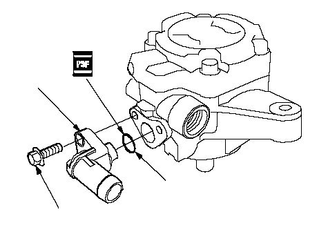 11 N·m (1.1 kgf·m, 8 lbf·ft)BA 11 N·m (1.1 kgf·m, 8 lbf·ft)BA |
| 45. | Install the inlet joint on the pump housing.
|
| 46. | Install the pulley (A), then loosely install the pulley nut (B). Hold the steering pump in a vise with soft jaws (C). Be careful not to damage the pump housing with the jaws of the vise.
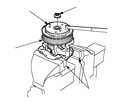 B B
64 N·m
(6.5 kgf·m, 47 lbf·ft)A07ZAB-S5A0100C |
| 47. | Hold the pulley with the special tool, and tighten the pulley nut to specified torque.
|
| 48. | Check that the pump turns smoothly by turning the pulley. If it turns hard, loosen the four flange bolts on the cover, then retightening them in the same manner as in the step 35. Turning the pump again by hand.
|