ABS System Description (ABS)
ABS System Description
ABS Control Unit Inputs and Outputs for 25P Connector
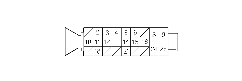 Wire side of female terminals
| Terminal number | Wire color | Terminal sign | Description | Measurement (Disconnect the ABS control unit 25P connector) | |||||
|---|---|---|---|---|---|---|---|---|---|
| Terminals | Conditions | Voltage | |||||||
| 2 | ORN/BLK | FR +B | Detects right-front wheel sensor signal | ——— | ——— | ——— | |||
| 3 | BRN/ WHT | FL-GND | Detects left-front wheel sensor signal | ——— | ——— | ——— | |||
| 4 | WHT/ BLK | STOP | Detects brake switch signal | 4- GND | Brake pedal | Pressed | Battery Voltage | ||
| Released | Below 0.3 V | ||||||||
| 5 | RED | RL-GND | Detects left-rear wheel sensor signal | ——— | ——— | ——— | |||
| 6 | GRN/ YEL | RR +B | Detects right-rear wheel sensor signal | ——— | ——— | ——— | |||
| 8 | WHT | +B-FSR | Power source for the fail-safe relay | 8- GND | At all times | Battery Voltage | |||
| 9 | WHT/ RED | +B-MR | Power source for the motor relay | 9- GND | At all times | Battery Voltage | |||
| Terminal number | Wire color | Terminal sign | Description | Measurement (Disconnect the ABS control unit 25P connector) | |||||
|---|---|---|---|---|---|---|---|---|---|
| Terminals | Conditions | Voltage | |||||||
| 10 | BLU | DIAG-K | Communications with Honda PGM Tester or HDS | ——— | ——— | ——— | |||
| 11 | BLK/ RED | EBD | Drives brake system indicator | 11- GND | Brake system indicator | OFF | Battery voltage | ||
| ON | Battery voltage (via brake fuild level switch or parking brake switch) | ||||||||
| ON | Below 0.3 V (via ABS control unit) | ||||||||
| 12 | BLU/ WHT | FL +B | Detects left-front wheel sensor signal | ——— | ——— | ——— | |||
| 13 | BRN | SCS | DTC indication | ——— | ——— | ——— | |||
| 14 | YEL/ RED | RL +B | Detects left-rear wheel sensor signal | ——— | ——— | ——— | |||
| 15 | BLU/ YEL | RR-GND | Detects right-rear wheel sensor signal | ——— | ——— | ——— | |||
| 16 | YEL | IG1 | Power source for activating the system | 16- GND | Ignition switch ON (II) | Battery Voltage | |||
| 18 | PNK | FR-GND | Detects right-front wheel sensor signal | ——— | ——— | ——— | |||
| 21 | BLU/ RED | ABS | Drives ABS indicator | 21- GND | ABS indicaor (Ignition switch ON (II)) | ON | About 6 V | ||
| OFF | Below 0.3 V | ||||||||
| 24 | BLK | GND | Ground for the ABS modulator-control unit | ——— | ——— | ——— | |||
| 25 | BLK | MR-GND | Ground for the pump motor | ——— | ——— | ——— | |||
Features
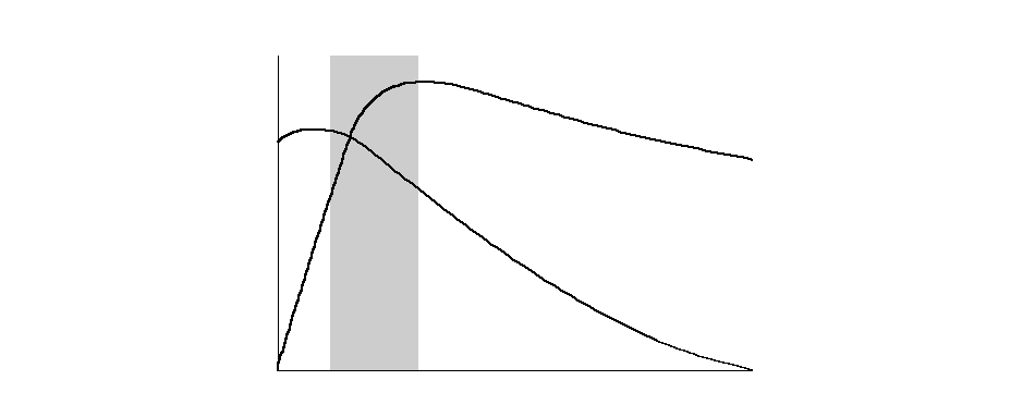
When the brake pedal is pressed during driving, the wheels can lock before the vehicle comes to a stop. In such an event, the maneuverability of the vehicle is reduced if the front wheels are locked, and the stability of the vehicle is reduced if the rear wheels are locked, creating an extremely unstable condition. The ABS precisely controls the slip rate of the wheels to ensure maximum grip force from the tyres, thereby ensuring the maneuverability and stability of the vehicle.
The ABS calculates the slip rate of the wheels based on the vehicle speed and the wheel speed, then it controls the brake fluid pressure to reach the target slip rate.
Grip Force of Tire and Road Surface
 COEFFICIENT OF
 FRICTIONTARGET SLIP RATEROTATIONAL
DIRECTIONRADIAL
DIRECTION
OF THE
ROTATIONAL
DIRECTIONSLIP RATE
| COMPONENTS | MAIN FUNCTION | |
|---|---|---|
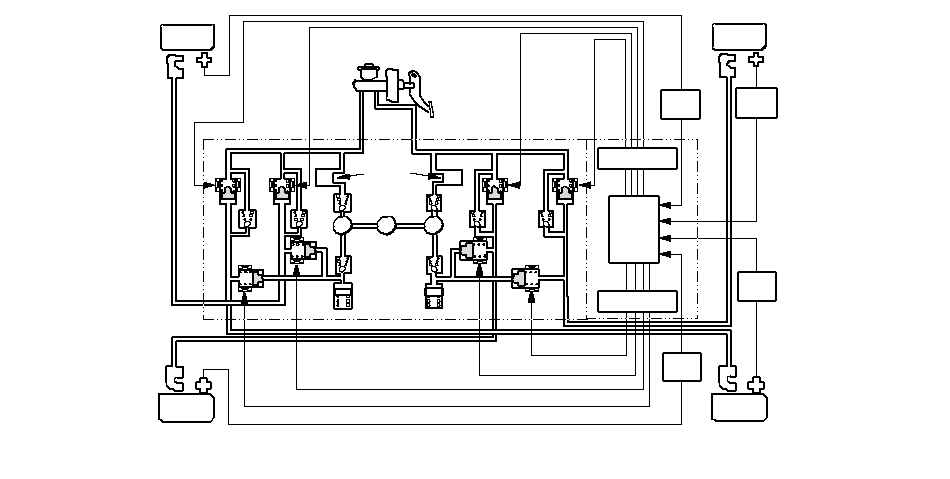
| Wheel sensor | The wheel sensor outputs the speed signal to the ABS control unit according to the encoder's (pulser's) rotation speed. | |
| Modulator- control unit | ABS control unit | The ABS control unit processes the signal from the wheel sensor, then outputs the ABS control signal to the modulator unit. |
| Modulator unit | The modulator unit receives the control signal, then controls brake fluid pressure for each wheel. | |
| Motor relay (inside of the ABS control unit) | The motor relay drives the ABS pump motor. | |
| ABS fail-safe relay (inside of the ABS control unit) | The ABS fail-safe relay cuts the power to the solenoid valve when a problem is detected. | |
 WHEEL
WHEELSENSOR
SIGNALSOLENOID VALVE
CONTROLWHEEL
SENSOR
SIGNALWHEEL
SENSORRLNO: Normally Open
NC: Normally ClosedWHEEL
SENSOR
SIGNALWHEEL
SENSOR
SIGNALWHEEL
SENSORRRABS
CONTROL
UNITSOLENOID VALVE
CONTROLMASTER CYLINDERNONONCPUMPMOTORPUMPPMPDAMPING
CHAMBERRESERVOIRNCNCWHEEL
SENSORFLWHEEL
SENSORFRNCNONORESERVOIRMODULATOR
UNITABS MODULATOR-
CONTROL UNIT
ABS Control Unit
Main Control
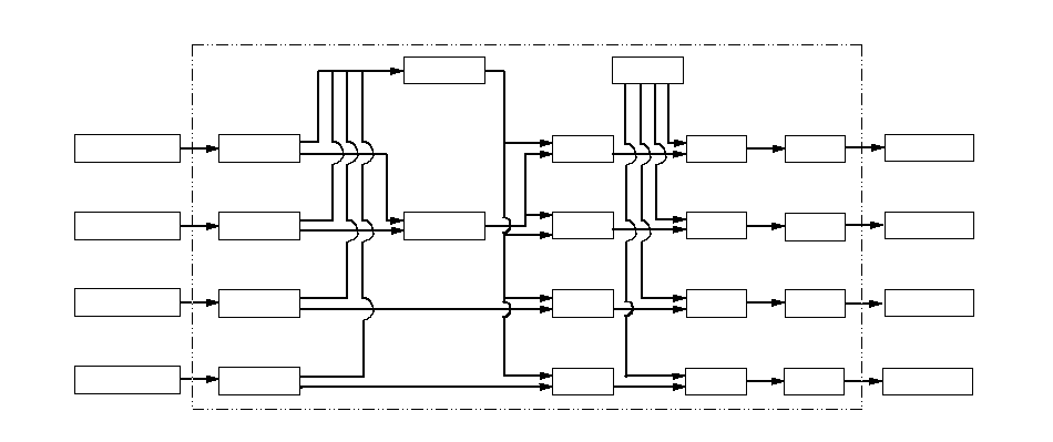
The ABS control unit detects the wheel speed based on the wheel sensor signal it received, then it calculates the vehicle speed based on the detected wheel speed. The control unit detects the vehicle speed during deceleration based on the rate of deceleration.
The ABS control unit calculates the slip rate of each wheel, and transmits the control signal to the modulator unit solenoid valve when the slip rate is high.
The hydraulic control has three modes: pressure reducing, pressure retaining, and pressure intensifying.
 LEFT-REAR
WHEEL SENSOR RIGHT-REAR
WHEEL SENSOR LEFT-FRONT
WHEEL SENSOR RIGHT-FRONT
WHEEL SENSOR Detect
Wheel Speed Detect
Wheel Speed Detect
Wheel Speed Select Low
Speed Wheel Detect
Vehicle Speed Detect
Slip RateRIGHT-FRONT Detect
Slip RateLEFT-FRONT ABS
Control Drive
SolenoidRIGHT-REAR
SOLENOIDLEFT-REAR
SOLENOIDRIGHT-FRONT
SOLENOIDLEFT-FRONT
SOLENOIDABS CONTROL UNIT Detect
Wheel Speed ABS
Control Drive
Solenoid Drive
Solenoid Drive
Solenoid Detect
Slip RateRIGHT-REAR ABS
Control Detect
Slip RateLEFT-REAR ABS
ControlReference
Slip Rate
Electronic Brake Distribution (EBD) Control
The electronic brake distribution (EBD) function helps control vehicle braking by adjusting the rear brake force before the ABS operates. Based on wheel sensor signals, the ABS control unit uses the modulator to control the rear brakes individually. When the rear wheel speed is less than the front wheel speed, the ABS control unit retains the current rear brake fluid pressure by closing the inlet valve in the modulator. As the rear wheel speed increases and approaches the front wheel speed, the control unit increases the rear brake fluid pressure by momentarily opening the inlet valve. This whole process is repeated very rapidly. While this is happening, there is kickback at the brake pedal.During self-diagnosis, if the ABS control unit detects a problem that affects the EBD, it turns on the brake system indicator and the ABS indicator.
Self-diagnosis Function
| 1. | The ABS control unit is equipped with a CPU and a monitor IC. They check each other for problems. |
| 2. | The CPU check the system circuits. |
| 3. | The ABS control unit turns on the ABS and possibly the brake system indicator when the unit detects a problem, and the unit stops ABS operation. |
| 4. | The self-diagnosis can be classified into these two categories:
|
On-board Diagnosis Function
The ABS can be diagnosed with the Honda PGM or HDS Tester.The ALB Checker cannot be used with this system. For air bleeding, and checking wheel sensor signals, use the Honda PGM or HDS Tester. See the Honda PGM Tester user's manual or HDS help menu for specific operating instructions.
ABS Modulator
The ABS modulator consists of the inlet solenoid valve, outlet solenoid valve, reservoir, pump, and the pump motor. The modulator reduces the caliper fluid pressure directly. It is a circulating-type modulator because the brake fluid circulates through the caliper, reservoir, and the master cylinder. The hydraulic control has three modes: normal braking, pressure retaining, and pressure reducing. The hydraulic circuit is an independent four channel type, one channel for each wheel.
Shown in normal braking mode
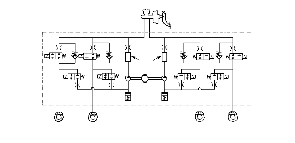 MODULATOR UNITRLFRFLRRMASTER CYLINDEROUTIN : INLET VALVE (NORMALLY OPEN)
OUT: OUTLET VALVE (NORMALLY CLOSED)OUTMOTORPUMPOUTININININOUTMRESERVOIRDAMPING
CHAMBERPUMPRESERVOIR
| Normal braking mode: | Inlet valve open, outlet valve closed Master cylinder fluid is pumped out to the caliper. |
| Pressure retaining mode: | Inlet valve closed, outlet valve closed Caliper fluid is retained by the inlet valve and outlet valve. |
| Pressure reducing mode: | Inlet valve closed, outlet valve open Caliper fluid flows through the outlet valve to the reservoir. When in pressure reducing mode, the pump motor is ON. The reservoir fluid is pumped out by the pump, through the damping chamber, to the master cylinder. When stopping ABS operation, the pump motor is OFF. |
Wheel Sensors
The wheel sensors are the magnetic contactless type. The wheel sensors detect changing of magnetic polarity on the magnetic encoder contained inside the front wheel bearings. The ABS control unit calculates the wheel speed based on signals received from the wheel sensor.
NOTE: The front wheel bearings are directional.
Wheel Speed and Modulator Control
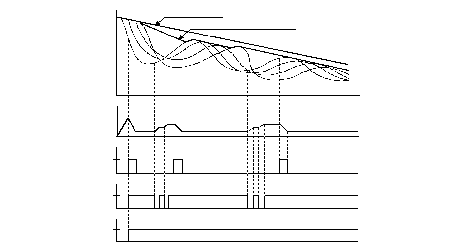 SPEEDVEHICLE SPEEDREFERENCE VEHICLE SPEEDPRESSUREONOUTLET
VALVEOFFINLET
VALVEONOFFMOTORONOFFWHEEL SPEEDTIME