Climate Control System Description (With Climate Control)
Climate Control System Description
The air conditioning system removes heat from the passenger compartment by circulating refrigerant through the system as shown below.
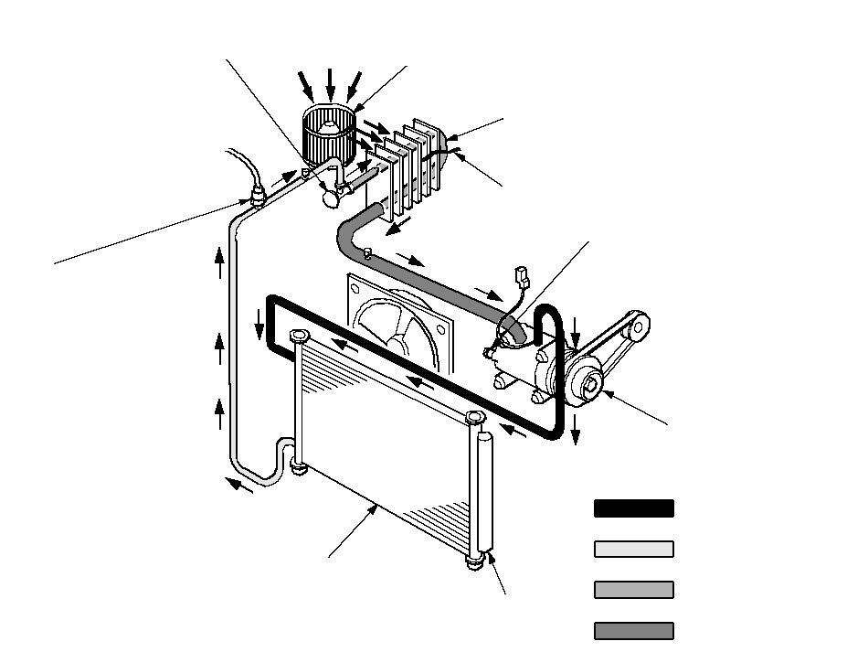 EVAPORATOR EXPANSION VALVE
(Meters the required amount of
refrigerant into the evaporator)RECEIVER/DRYER
(Traps debris, and
removes moisture)A/C COMPRESSOR
(Suction and compression)A/C CONDENSER
(Radiation of heat)A/C PRESSURE SWITCH
When the refrigerant is below
196 kPa (2.0 kgf/cm2, 28 psi)
or above 3,140 kPa (32 kgf/cm2 ,
455 psi), the A/C pressure
switch opens the circuit to
the A/C switch and stops the
air conditioning to protect the
compressor.BLOWER FANEVAPORATOR
(Absorption of heat)EVAPORATOR TEMPERATURE
SENSORA/C COMPRESSOR RELIEF VALVE
(Relieves pressure at the compressor
when the pressure is too high)HIGH PRESSURE VAPORHIGH PRESSURE LIQUIDLOW PRESSURE LIQUIDLOW PRESSURE VAPOR
- Do not mix refrigerants CFC-12 (R-12) and HFC-134a (R-134a). They are not compatible.
- Use only the recommended polyalkyleneglycol (PAG) refrigerant oil (KEIHIN SP-10) designed for the R-134a compressor. Intermixing the recommended (PAG) refrigerant oil with any other refrigerant oil will result in compressor failure.
- All A/C system parts (compressor, discharge line, suction line, evaporator, condenser, receiver/dryer, expansion valve, O-rings for joints) have to be designed for refrigerant R-134a. Do not exchange with R-12 parts.
- Use a halogen gas leak detector designed for refrigerant R-134a.
- R-12 and R-134a refrigerant servicing equipment are not interchangeable. Use only a recovery/recycling/charging station that is U.L.-listed and is certified to meet the requirements of SAE J2210 to service R-134a air conditioning system.
- Always recover the refrigerant R-134a with an approved recovery/recycling/charging station before disconnecting any A/C fitting.
Climate Control Unit Inputs and Outputs
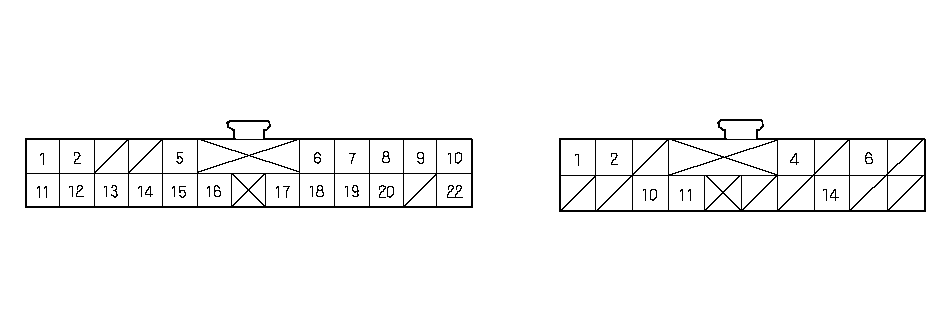 CLIMATE CONTROL UNIT CONNECTORSCONNECTOR A(22P)CONNECTOR B(16P)Wire side of female terminals
| Cavity | Wire color | Signal | |
|---|---|---|---|
| 1 | PNK/BLK | DRIVER'S AIR MIX POTENTIAL | INPUT |
| 2 | YEL | PASSENGER'S AIR MIX POTENTIAL | INPUT |
| 3 | ——— | ——— | ——— |
| 4 | ——— | ——— | ——— |
| 5 | BLU | A/C PRESSURE SWITCH | OUTPUT |
| 6 | YEL/BLU | MODE DEF | OUTPUT |
| 7 | YEL/RED | MODE VENT | OUTPUT |
| 8 | GRN | DRIVER'S AIR MIX COOL | OUTPUT |
| 9 | PNK/BLU | DRIVER'S AIR MIX HOT | OUTPUT |
| 10 | YEL/BLK | PASSENGER'S AIR MIX COOL | OUTPUT |
| 11 | LT BLU | IN-CAR TEMPERATURE SENSOR | INPUT |
| 12 | PNK | OUTSIDE AIR TENPERATURE SENSOR | INPUT |
| 13 | ORN | SUNLIGHT SENSOR | INPUT |
| 14 | BRN | EVAPORATOR TEMPERATURE SENSOR | INPUT |
| 15 | RED [RED/BLK] | SENSOR COMMON GROUND | OUTPUT |
| 16 | YEL/GRN | MODE 4 | INPUT |
| 17 | WHT/BLU | MODE 3 | INPUT |
| 18 | RED/BLU | MODE 2 | INPUT |
| 19 | RED/YEL | MODE 1 | INPUT |
| 20 | GRY | DRIVER'S AIR MIX POTENTIAL +5 V | OUTPUT |
| 21 | ——— | ——— | ——— |
| 22 | LT GRN | PASSENGER'S AIR MIX HOT | OUTPUT |
| [ ]: RHD |
| Cavity | Wire color | Signal | |
|---|---|---|---|
| 1 | BLU/YEL | POWER TRANSISTOR | OUTPUT |
| 2 | BLU/RED | BLOWER FEEDBACK | INPUT |
| 3 | ——— | ——— | ——— |
| 4 | BLK/YEL | IG2 (Power) | INPUT |
| 5 | ——— | ——— | ——— |
| 6 | BLK | GROUND | INPUT |
| 7 | ——— | ——— | ——— |
| 8 | ——— | ——— | ——— |
| 9 | ——— | ——— | ——— |
| 10 | GRN/WHT | FRESH | OUTPUT |
| 11 | LT GRN/RED | RECIRCULATE | OUTPUT |
| 12 | ——— | ——— | ——— |
| 13 | ——— | ——— | ——— |
| 14 | LT BLU | MULTIPLEX INTEGRATED CONTROL UNIT | INPUT |
| 15 | ——— | ——— | ——— |
| 16 | ——— | ——— | ——— |