Honda Accord ESM 2003 · Service Manual Service Manual 2003

Multiplex Integrated Control Unit Input Test (4D)

Multiplex Integrated Control Unit Input Test

1.Remove the left side kick panel (LHD type) or right side kick panel (RHD type).

2.Disconnect the under-dash fuse/relay box connectors D, E, H, I, J, K, N, P and X.
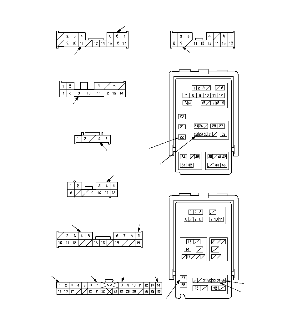
SEA3EK0J34600041951FCAD01UNDER-DASH FUSE/RELAY BOX
CONNECTOR D (17P)
UNDER-DASH FUSE/RELAY BOX
CONNECTOR E (16P)
UNDER-DASH FUSE/RELAY BOX
CONNECTOR H (14P)
UNDER-DASH FUSE/RELAY BOX
CONNECTOR I (5P)
UNDER-DASH FUSE/RELAY BOX
CONNECTOR K (12P)
UNDER-DASH FUSE/RELAY BOX
CONNECTOR J (21P)
UNDER-DASH FUSE/RELAY BOX
CONNECTOR P (30P)
UNDER-DASH FUSE/RELAY BOX
CONNECTOR N (45P)
UNDER-DASH FUSE/RELAY BOX
CONNECTOR X (39P)
BLUYELBLKBLKGRN/REDGRN/WHTORN*1BRN*1YELWHTLT BLULT BLUWHTYELNOTE: All connectors are wire side of female terminals.BRN/REDORN*2BRN*2*1: LHD type*2: RHD type

3.Inspect the connector and socket terminals to be sure they are all making good contact.

  • If the terminals are bent, loose or corroded, repair them as necessary, and recheck the system.
  • If the terminals look OK, go to 4.

4.With the connectors still disconnected from the under-hood fuse/relay box, make these input tests at the connector(s).

  • If any test indicates a problem, find and correct the cause, then recheck the system.
  • If all the input tests prove ok, go to 5.

Cavity Wire Test condition Test: Desired result Possible cause if result is not obtained 
H9 BLK Under all conditions Check for continuity to ground:
There should be continuity. 
  • Poor ground (G601)
  • An open in the wire
 
P1*1
P14*2 
BRN Under all conditions Check for continuity to ground:
There should be continuity. 
  • Poor ground (G502)
  • An open in the wire
 
E9 BLK Under all conditions Check for continuity to ground:
There should be continuity. 
  • Poor ground (G601)
  • An open in the wire
 
D6
·
J9
·
X34 
YEL Ignition switch ON (II) Check for voltage to ground:
There should be battery voltage. 
  • Blown No. 21 (7.5A) fuse in the under-dash fuse/relay box
  • An open in the wire
 
K4 GRN/WHT Under all conditions Check for voltage to ground:
There should be battery voltage. 
  • Blown No. 27 (20A) fuse in the under-dash fuse/relay box
  • An open in the wire
 
X35 WHT Under all conditions Check for voltage to ground:
There should be battery voltage. 
  • Blown No. 7 (10A) fuse in the under-dash fuse/relay box
  • An open in the wire
 
N22 LT BLU Under all conditions Check for continuity between terminal N22 and the climate control unit B (16P) connector terminal No. 14:
There should be continuity. 
  • An open in the wire
 
Climate control unit B (16P) connector disconnected Check for continuity to ground:
There should be no continuity. 
  • Short to ground
 
J4 BRN/RED Under all conditions Check for continuity between terminal J4 and power window master switch 23P connector terminal No. 16:
There should be continuity. 
  • An open in the wire
 
Power window master switch 23P connector disconnected Check for continuity to ground:
There should be no continuity. 
  • Short to ground
 
D11 BLU Under all conditions Check for continuity between terminal D11 and relay module J (10P) connector terminal No. 7:
There should be continuity. 
  • An open in the wire
 
Relay module J (10P) connector disconnected Check for continuity to ground:
There should be no continuity. 
  • Short to ground
 
X27 LT GRN Under all conditions Check for continuity between terminal X27 and wiper/washer switch 8P connector terminal No. 4:
There should be continuity. 
  • An open in the wire
 
Wiper/washer switch 8P connector disconnected Check for continuity to ground:
There should be no continuity. 
  • Short to ground
 
N28 WHT Under all conditions Check for continuity between terminal N28 and gauge assembly (30P) connector terminal No. 25:
There should be continuity. 
  • An open in the wire
 
Gauge control module B (30P) connector disconnected Check for continuity to ground:
There should be no continuity. 
  • Short to ground
 

*1: LHD type 
*2: RHD type 

5.Reconnect the connectors to the under-dash fuse/relay box, and make sure these input tests at the appropriate connectors on the under-dash fuse/relay box.

  • If any test indicates a problem, find and correct the cause, then recheck the system.
  • If all the input tests prove OK, the multiplex integrated contorl unit must be faulty, replace the under-dash fuse/relay box assembly.

Cavity Wire Test condition Test: Desired result Possible cause if result is not obtained 
P7*1
P8*2 
ORN Under all conditions Attach to ground: The ignition key light should come on. 
  • Blown No. 13 (20A) fuse in the under-hood fuse/relay box
  • Blown LED
  • An open in the wire
 
I4 GRN/RED Ceiling light switch in the middle position, all doors closed Attach to ground: The ceiling light should come on. 
  • Blown No. 6 (7.5A) fuse in the under-dash fuse/relay box
  • Faulty ceiling light
  • An open in the wire
 

*1: LHD type 
*2: RHD type