Fuel and Emissions System Description (5D)
Fuel and Emissions System Description
Electronic Control System
The functions of the fuel and emission control systems are managed by the engine control module (ECM) on vehicles with manual transmissions or the powertrain control module (PCM) on vehicles with automatic transmissions.
Fail-safe Function
When an abnormality occurs in the signal from a sensor, the ECM/PCM ignores that signal and assumes a pre-programmed value for that sensor that allows the engine to continue to run.Back-up Function
When an abnormality occurs in the ECM/PCM, the injectors are controlled by a back-up circuit independent of the system to permit minimal driving.Self-diagnosis
When an abnormality occurs in the signal from a sensor, the ECM/PCM supplies ground for the malfunction indicator lamp (MIL) and stores the diagnostic trouble code (DTC) in erasable memory. When the ignition is first turned on, the ECM/PCM supplies ground to the MIL for 2 seconds to check the MIL bulb condition.Two Driving Cycle Detection Method
To prevent false indications, the ‘‘two driving cycle detection method'' is used for some self-diagnostic functions. When an abnormality occurs, the ECM/PCM stores it in its memory. When the same abnormality recurs after the ignition switch is turned OFF and ON (II) again, the ECM/PCM turns on the MIL.Self Shut Down Mode (SSD)
After the ignition switch is turned off, the ECM/PCM stays ON (up to 15 minutes).If the ECM/PCM connector is disconnected during this mode, the ECM/PCM may be damaged.
To cancel this mode, disconnect the negative cable from the battery or jump the SCS line with the HDS after the ignition switch is turned off.
ECM/PCM Inputs and Outputs at Connector A (31P)
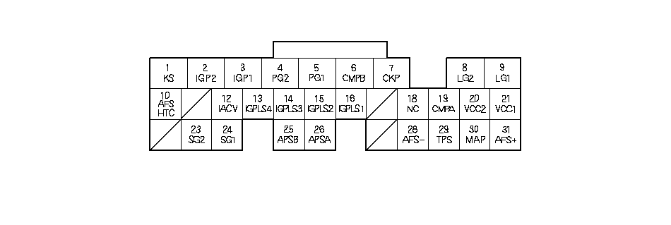 Wire side of female terminals
| Terminal number | Wire color | Terminal name | Description | Signal |
|---|---|---|---|---|
| 1 | RED/BLU | KS (KNOCK SENSOR) | Deyects knock sensor signal | With engine knocking: pulses |
| 2 | YEL/BLK | IGP2 (POWER SOURCE) | Power source for ECM/PCM circuit | With ignition switch ON (II): battery voltage With ignition switch OFF: about 0 V |
| 3 | YEL/BLK | IGP1 (POWER SOURCE) | Power source for ECM/PCM circuit | With ignition switch ON (II): battery voltage With ignition switch OFF: about 0 V |
| 4 | BLK | PG2 (POWER GROUND) | Ground circuit for the ECM/PCM | Less than 1.0 V at all times |
| 5 | BLK | PG1 (POWER GROUND) | Ground circuit for the ECM/PCM | Less than 1.0 V at all times |
| 6 | GRN | CMP B (CAMSHAFT POSITION SENSOR B) | Detects CMP sensor B signal | With engine running: pulses With the ignition switch ON (II): about 5 V |
| 7 | BLU | CKP (CRANKSHAFT POSITION SENSOR) | Detects CKP sensor signal | With engine running: pulses With the ignition switch ON (II): about 5 V |
| 8 | BRN/YEL | LG2 (LOGIC GROUND) | Ground circuit for the ECM/PCM | Less than 1.0 V at all times |
| 9 | BRN/YEL | LG1 (LOGIC GROUND) | Ground circuit for the ECM/PCM | Less than 1.0 V at all times |
| 10 | GRN | AFSHTC (AIR FUEL RATIO (A/F) SENSOR HEATER CONTROL) | Drives A/F sensor heater | With ignition switch ON (II): battery voltage With fully warmed up engine running: about 0 V |
| 12*1 | BLK/RED | IACV (IDLE AIR CONTROL (IAC) VALVE) | Drives IAC valve | With engine running: duty controlled |
| 13 | BRN | IGPLS4 (No. 4 IGNITION COIL PULSE) | Drives No. 4 ignition coil | With ignition switch ON (II): about 0 V With engine running: pulses |
| 14 | WHT/BLU | IGPLS3 (No. 3 IGNITION COIL PULSE) | Drives No. 3 ignition coil | |
| 15 | BLU/RED | IGPLS2 (No. 2 IGNITION COIL PULSE) | Drives No. 2 ignition coil | |
| 16 | YEL/GRN | IGPLS1 (No. 1 IGNITION COIL PULSE) | Drives No. 1 ignition coil | |
| 18 | BLK/BLU | NC (COUNTERSHAFT SPEED SENSOR) | Detects countershaft speed sensor signal | With ignition switch ON (II): about 0 V or about 5 V While driving: about 2.5 V |
| 19 | BLU/WHT | CMP A (CAMSHAFT POSITION SENSOR A) | Detects CMP sensor A signal | With engine running: pulses With ignition switch ON (II): about 5 V |
| *1: | K20A6 engine |
ECM/PCM Inputs and Outputs at Connector A (31P)
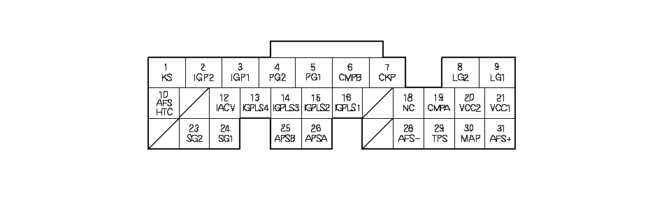 Wire side of female terminals
| Terminal number | Wire color | Terminal name | Description | Signal |
|---|---|---|---|---|
| 20 | YEL/BLU | VCC2 (SENSOR VOLTAGE) | Provides sensor voltage | With ignition switch ON (II): about 5 V With ignition switch OFF: about 0 V |
| 21 | YEL/RED | VCC1 (SENSOR VOLTAGE) | Provides sensor voltage | With ignition switch ON (II): about 5 V With ignition switch OFF: about 0 V |
| 23 | GRN/YEL | SG2 (SENSOR GROUND) | Sensor ground | Less than 1.0 V at all times |
| 24 | GRN/WHT | SG1 (SENSOR GROUND) | Sensor ground | Less than 1.0 V at all times |
| 25*2 | RED/YEL | APSB (ACCELERATOR PEDAL POSITION (APP) SENSOR B) | Detects APP sensor B signal | With ignition switch ON (II) and accelerator pedal pressed: about 2.3 V With ignition switch ON (II) and accelerator pedal released: about 0.2 V |
| 26*2 | RED/BLU | APSA (ACCELERATOR PEDAL POSITION (APP) SENSOR A) | Detects APP sensor A signal | With ignition switch ON (II) and accelerator pedal pressed: about 4.5 V With ignition switch ON (II) and accelerator pedal pressed: about 0.5 V |
| 28 | RED/YEL | AFS - (AIR FUEL RATIO (A/F) SENSOR, SENSOR 1 - SIDE) | Detects A/F sensor (sensor 1) signal | |
| 29*1 | RED/BLK | TPS (THROTTLE POSITION SENSOR) | Detects TP sensor signal | With throttle fully open: about 4.5 V typically With throttle fully closed: about 0.5 V |
| 30 | GRN/RED | MAP (MANIFOLD ABSOLUTE PRESSURE SENSOR) | Detects MAP sensor signal | With ignition switch ON (II): about 3V At idle: about 1.0 V (depending on engine speed) |
| 31 | RED | AFS + (AIR FUEL RATIO (A/F) SENSOR, SENSOR 1 + SIDE) | Detects A/F sensor (sensor 1) signal |
| *1: | K20A6 engine |
| *2: | K24A3 engine |
ECM/PCM Inputs and Outputs at Connector B (24P)
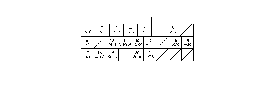 Wire side of female terminals
| Terminal number | Wire color | Terminal name | Description | Signal |
|---|---|---|---|---|
| 1 | BLU/WHT | VTC (VTC OIL CONTROL SOLENOID VALVE) | Drives VTC oil control solenoid valve | With ignition switch ON (II): 0 V |
| 2 | YEL | INJ4 (No. 4 INJECTOR) | Drives No. 4 injector | At idle: duty controlled With the ignition switch ON (II): battery voltage |
| 3 | BLU | INJ3 (No. 3 INJECTOR) | Drives No. 3 injector | |
| 4 | RED | INJ2 (No. 2 INJECTOR) | Drives No. 2 injector | |
| 5 | BRN | INJ1 (No. 1 INJECTOR) | Drives No. 1 injector | |
| 6 | GRN/YEL | VTS (VTEC SOLENOID VALVE) | Drives VTEC solenoid valve | At idle: about 0 V |
| 8 | RED/WHT | ECT (ENGINE COOLANT TEMPERATURE SENSOR) | Detects ECT sensor signal | With ignition switch ON (II): about 0.1-4.8 V (depending on engine coolant temperature) With fully warmed up engine: about 0.5-0.7 V |
| 10 | WHT/BLU | ALTL (ALTERNATOR L SIGNAL) | Detects alternator signal | With ignition switch ON (II): about 0 V With engine running: battery voltage |
| 11 | BLU/BLK | VTPSW (VTEC OIL PRESSURE SWITCH) | Detects VTEC oil pressure switch signal | With engine at low engine speed: about 0 V With engine at high engine speed: battery voltage |
| 12*1 | WHT/BLK | EGRP (EXHAUST GAS RECIRCULATION (EGR) VALVE POSITION SENSOR)) | Detects EGR valve position sensor signal | With engine running: 1.2 V-3.0 V (depending on EGR valve lift) |
| 13 | WHT/RED | ALTF (ALTERNATOR FR SIGNAL) | Detects alternator FR signal | With engine running: about 0 V-5 V (depending on electrical load) |
| 15 | BLU/YEL | MCS (ENGINE MOUNT CONTROL SOLENOID VALVE) | Drives engine mount control solenoid valve | At idle: about 0 V Above idle: battery voltage With ignition switch ON (II): battery voltage |
| 16*1 | BLU/RED | EGR (EXHAUST GAS RECIRCULATION (EGR) VALVE) | Drives EGR valve | With EGR operating: duty controlled With EGR not operating: about 0 V |
| 17 | RED/YEL | IAT (INTAKE AIR TEMPERATURE SENSOR) | Detects IAT sensor signal | With ignition switch ON (II): about 0.1 V-4.8 V (depending on intake air temperture) |
| 18 | WHT/GRN | ALTC (ALTERNATOR CONTROL) | Sends alternator control signal | With engine running: and fully warmed up: about 8 V |
| 19*2 | GRN | SEFD (THROTTLE ACTUATOR CONTROL SERIAL SIGNAL) | Sends throttle actuator control serial signal | |
| 20*2 | BLU | SEDF (THROTTLE ACTUATOR CONTROL SERIAL SIGNAL) | Detects throttle actuator control serial signal | |
| 21 | YEL/BLU | PCS (EVAPORATIVE EMISSION CANISTER PURGE VALVE) | Drives EVAP canister purge valve | With engine running, engine coolant below 65°C (149°F): battery voltage With engine running, engine coolant above 65°C (149°F): duty controlled |
| *1: | K20A6 engine |
| *2: | K24A3 engine |
PCM Inputs and Outputs at Connector C (22P)
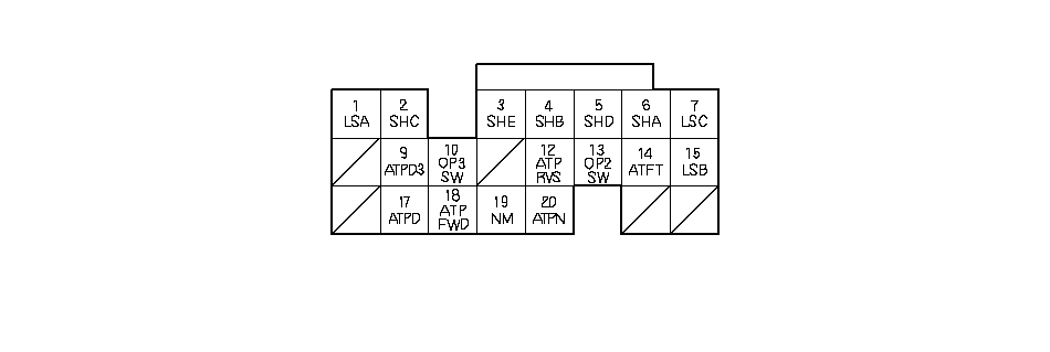 Wire side of female terminals
| Terminal number | Wire color | Terminal name | Description | Signal |
|---|---|---|---|---|
| 1*4 | RED/BLK | LSA (A/T CLUTCH PRESSURE CONTROL SOLENOID VALVE A) | Drives A/T clutch pressure control solenoid valve A | With ignition switch ON (II): duty controlled |
| 2*4 | GRN | SHC (SHIFT SOLENOID VALVE C) | Drives shift solenoid valve C | With engine running in Neutral and [1] position, or in D or D3 position (in 1st, 3rd and 5th gears): battery voltage With engine running in Park, R position, [2], or D or D3 position (in 2nd, 4th gears): about 0 V |
| 3*4 | YEL | SHE (SHIFT SOLENOID VALVE E) | Drives shift solenoid valve E | With engine running in Park, R position: battery voltage With engine running in Neutral position, or in D, D3, [2], and [1] position: about 0 V |
| 4*4 | GRN/WHT | SHB (SHIFT SOLENOID VALVE B) | Drives shift solenoid valve B | With engine running in Park, R, Neutral [2], and [1] position, or D, D3 position (in 1st, 2nd gears): battery voltage With engine running in D, D3 position (in 3rd, 4th, 5th gears): about 0 V |
| 5*4 | GRN/RED | SHD (SHIFT SOLENOID VALVE D) | Drives shift solenoid valve D | With engine running in [2] or D, D3 position (in 2nd, 5rd gears): battery voltage With engine running in Park, R, Neutral, [1] position, or D, D3 position (in 1st, 3rd, 4th, gears): about 0 V |
| 6*4 | BLU/BLK | SHA (SHIFT SOLENOID VALVE A) | Drives shift solenoid valve A | With engine running in R and [1] position, or D, D3 position (in 1st, 4th, 5th gears): battery voltage With engine running in Park, Neutral and [2] position, or D, D3 position (in 2nd, 3rd gears): about 0 V |
| 7*4 | BLU/YEL | LSC (A/T CLUTCH PRESSURE CONTROL SOLENOID VALVE C) | Drivers A/T clutch pressure control solenoid valve C | With the ignition switch ON (II): duty controlled |
| 9*4 | RED | ATPD3 (TRANSMISSION RANGE SWITCH D3 POSITION) | Detects transmission range switch D3 position signal input | In D3 position: about 0 V In any other positioin: battery voltage |
| 10*4 | BLU/WHT | OP3SW (3RD CLUTCH TRANSMISSION FLUID PRESSURE SWITCH) | Detects 3rd clutch transmission fluid pressure switch signal output | With ignition switch ON (II): about 5 V With 3rd clutch pressure: 0 V |
| 12*4 | RED/WHT | ATPRVS (TRANSMISSION RANGE SWITCH R POSITION) | Detects transmission range switch R position signal input | In R position: about 0 V In any other position: battery voltage |
| 13*4 | BLU/RED | OP2SW (2ND CLUTCH TRANSMISSION FLUID PRESSURE SWITCH) | Detects 2nd clutch transmission fluid pressure switch signal input | With ignition switch ON (II): about 5 V With 2nd clutch pressure: 0 V |
| 14*4 | RED/YEL | ATFT (ATF TEMPERATURE SENSOR) | Detects ATF temperature sensor signal input | With ignition switch ON (II): about 0.2 V-4.8 V (depending on ATF temperature) |
| *4: | A/T |
PCM Inputs and Outputs at Connector C (22P)
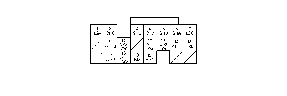 Wire side of female terminals
| Terminal number | Wire color | Terminal name | Description | Signal |
|---|---|---|---|---|
| 15*4 | BLU/WHT | LSB (A/T CLUTCH PRESSURE CONTROL SOLENOID VALVE B) | Drives A/T clutch pressure control solenoid valve B | With the ignition switch ON (II): duty controlled |
| 17*4 | YEL/GRN | ATPD (TRANSMISSION RANGE SWITCH D POSITION) | Detects transmission range switch D position signal | In D position: about 0 V In any other position: battery voltage |
| 18*4 | BLU/YEL | ATPFWD (TRANSMISSION RANGE SWITCH D/D3 POSITION) | Detects transmission range switch D, D3, [2] position signal | In D, D3, and [2] position: about 0 V In any other position: battery voltage |
| 19*4 | WHT/RED | NM (MAINSHAFT SPEED SENSOR) | Detects mainshaft speed sensor signal | With ignition switch ON (II): about 0 V or about 5 V With engine running in [N] position: about 2.5 V |
| 20*4 | RED/BLK | ATPN (TRANSMISSION RANGE SWITCH NEUTRAL POSITION) | Detects transmition range switch Neutral position signal | In Neutral position: about 0 V In any other position: battery voltage |
| *4: | A/T |
ECM/PCM Inputs and Outputs at Connector D (17P)
 Wire side of female terminals
| Terminal number | Wire color | Terminal name | Description | Signal |
|---|---|---|---|---|
| 2*4 | BRN | S MODE (SEQUENTIAL SPORT SHIFT MODE) | Detects sequential sportshift mode switch signal | In sequential sportshift mode (shift lever is positioned in sequential sportshift mode): 0 V In other than sequential sportshift mode: about 5 V |
| 3*4 | WHT | SUP (UP SHIFT SWITCH) | Detects upshift switch signal | In sequential sportshift mode and shift lever pushed toward upshift position: 0 V In sequential sportshift mode and shift lever in neutral position: about 5 V |
| 5*4 | GRN | ATPR (TRANSMISSION RANGE SWITCH R POSITION) | Detects transmission range switch R position signal | In R position: about 0 V In any other position: battery voltage |
| 6*4 | BLU | ATPP (TRANCMISSION RANGE SWITCH PARK POSITION) | Detects transmission range switch Park position signal | In Park position: about 0 V In any other position: battery voltage |
| 8*2 | BRN | BKSWNC (BRAKE PEDAL POSITION SWITCH) | Detects brake pedal position switch signal | With ignition switch ON (II) and brake pedal released: battery voltage With ignition switch ON (II) and brake pedal pressed: about 0 V |
| 9*4 | ORN | SDN (DOWN SHIFT SWITCH) | Detects downshift switch signal | In sequential sportshift mode and shift lever pushed toward downshift position: 0 V In sequential sportshift mode and shift lever in neutral position: about 5 V |
| 9*5 | LT BLU | CRMTCLS (CRUISE CLUTCH PEDAL POSITION SIGNAL) | Detects cruise clutch pedal position switch signal | With ignition switch ON (II) and clutch pedal released: about 0 V With ignition switch ON (II) and clutch pedal pressed: battery voltage |
| 10*4 | LT GRN | METINH (METER DISPLAY INHIBIT SIGNAL) | Send inhibit signal | With ignition switch ON (II): battery voltage |
| 11*3 | PNK | ATCCFWD (TRANSMISSION RANGE SWITCH CRUISE CONTROL FWD SIGNAL) | Send Park and D3 transmission range switch signal to cruise control unit | In D, D3 position: about 0 V In any other than D, D3 position: battery voltage |
| 12*3 | ORN(BLU)*6 | CCS (CRUISE CONTROL SIGNAL) | Detects cruise control signal | With cruise control: pulses |
| 15*2 | BRN | DBWRLY (THROTTLE ACTUATOR CONTROL MODULE RELAY) | Drives throttle actuator control module relay | With ignition switch ON (II): 0 V |
| *2: | K24A3 engine |
| *3: | K20A6 engine |
| *4: | A/T |
| *5: | K24A3 engine (M/T) |
| *6: | RHD model |
ECM/PCM Inputs and Outputs at Connector E (31P)
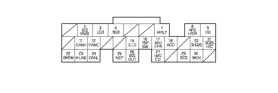 Wire side of female terminals
| Terminal number | Wire color | Terminal name | Description | Signal |
|---|---|---|---|---|
| 2*4 | GRN | SLS (SHIFT LOCK SOLENOID) | Drives shift lock solenoid | With ignition switch ON (II), in the Park position, brake pedal pressed, and accelerator released: 0 V |
| 2*5 | GRN | RVS (REVERSE LOCK SOLENOID VALVE) | Drives reverse lock solenoid valve | With vehicle speed below 15 km/h (9.4 mph): battery voltage With vehicle speed above 20 km/h (12.5 mph): 0 V |
| 3 | BLK | LG3 (LOGIC GROUND) | Ground for ECM/PCM control circuit | Less than 1.0 V at all times |
| 4 | BLK | SG3 (SENSOR GROUND) | Sensor ground | Less than 1.0 V at all times |
| 7 | RED/BLK | MRLY (PGM-FI MAIN RELAY) | Drives PGM-FI main relay 1 (FI MAIN) Power source for DTC memory | With ignition switch ON (II): about 0 V With ignition switch OFF: battery voltage |
| 8 | ORN | AFSHTCR (AIR FUEL RATIO (A/F) SENSOR HEATER CONTROL RELAY) | Drives A/F sensor heater relay | With ignition switch ON (II): 0 V |
| 9 | BLK/YEL | IG1 (IGNITION SIGNAL) | Detects ignition signal | With ignition switch ON (II): battery voltage With ignition switch OFF: about 0 V |
| 11 | WHT | CAN H (CAN COMMUNICATION SIGNAL HIGH) | Sends communication signal | With ignition switch ON (II): pulses |
| 12 | GRN | FANC (RADIATOR FAN CONTROL) | Drives radiator fan relay | With radiator fan running: about 0 V With radiator fan stopped: battery voltage |
| 15 | BLU | ELD (ELECTRICAL LOAD DETECTOR) | Detects ELD signal | With ignition switch ON (II): about 0.1 V-4.8 V (depending on electrical load) |
| 16 | GRY | PSPSW (POWER STEERING PRESSURE SWITCH SIGNAL) | Detects PSP switch signal | At idle with steering wheel straight ahead: 0 V At idle with steering wheel at full lock: battery voltage |
| 17 | WHT | IMO FPR (IMMOBILIZER FUEL PUMP RELAY) | Drives PGM-FI main relay 2 (FUEL PUMP) | 0 V for 2 seconds after turning ignition switch ON (II), then battery voltage |
| 18 | BRN | ACC (A/C CLUTCH RELAY) | Drives A/C clutch relay | With compressor ON: about 0 V With compressor OFF: battery voltage |
| 20 | WHT/RED | SHO2S (SECONDARY HEATED OXYGEN SENSOR (SECONDAY HO2S), SENSOR 2) | Detects secondary HO2S (sensor 2) signal | With throttle fully closed and idle with fully warmed up engine: above 0.6 V With throttle quickly closed: below 0.4 V |
| 21 | LT GRN | SO2SHTC (SECONDARY HEATED OXYGEN SENSOR (SECONDAY HO2S) HEATER CONTROL) | Drives secondary HO2S heater | With ignition switch ON (II): battery voltage With fully warmed up engine running: duty controlled |
| *4: | A/T |
| *5: | K24A3 engine |
ECM/PCM Inputs and Outputs at Connector E (31P)
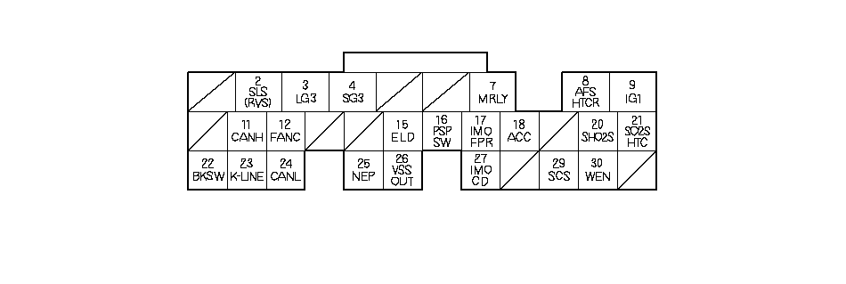 Wire side of female terminals
| Terminal number | Wire color | Terminal name | Description | Signal |
|---|---|---|---|---|
| 22 | WHT/BLK | BKSW (BRAKE PEDAL POSITION SWITCH) | Detects brake pedal position switch signal | With brake pedal released: about 0 V With brake pedal pressed: battery voltage |
| 23 | LT BLU | K-LINE | Sends and receives HDS signals | With ignition switch ON (II): pulses or battery voltage |
| 24 | RED | CANL (CAN COMMUNICATION SIGNAL LOW) | Sends the communication signal | With ignition switch ON (II): pulses |
| 25 | WHT | NEP(ENGINE SPEED PULSE) | Outputs engine speed pulse | With engine running: pulses |
| 26 | BLU | VSSOUT (VEHICLE SPEED SENSOR OUTPUT SIGNAL) | Sends vehicle speed sensor signal | Depending on vehicle speed: pulses With ignition switch ON (II): battery voltage |
| 27 | RED | IMOCD (IMMOBILIZER CODE) | Detects immobilizer signal | |
| 29 | BRN | SCS (SERVICE CHECK SIGNAL) | Detects service check signal | With the service check signal shorted using PGM Tester or HDS: about 0 V With the service check signal open: about 5 V |
| 30 | RED (RED/WHT)*6 | WEN (WRITE ENABLE SIGNAL) | Detects write enable signal | With ignition switch ON (II): about 0 V |
| *6: | RHD model |
Vacuum Hose Routing
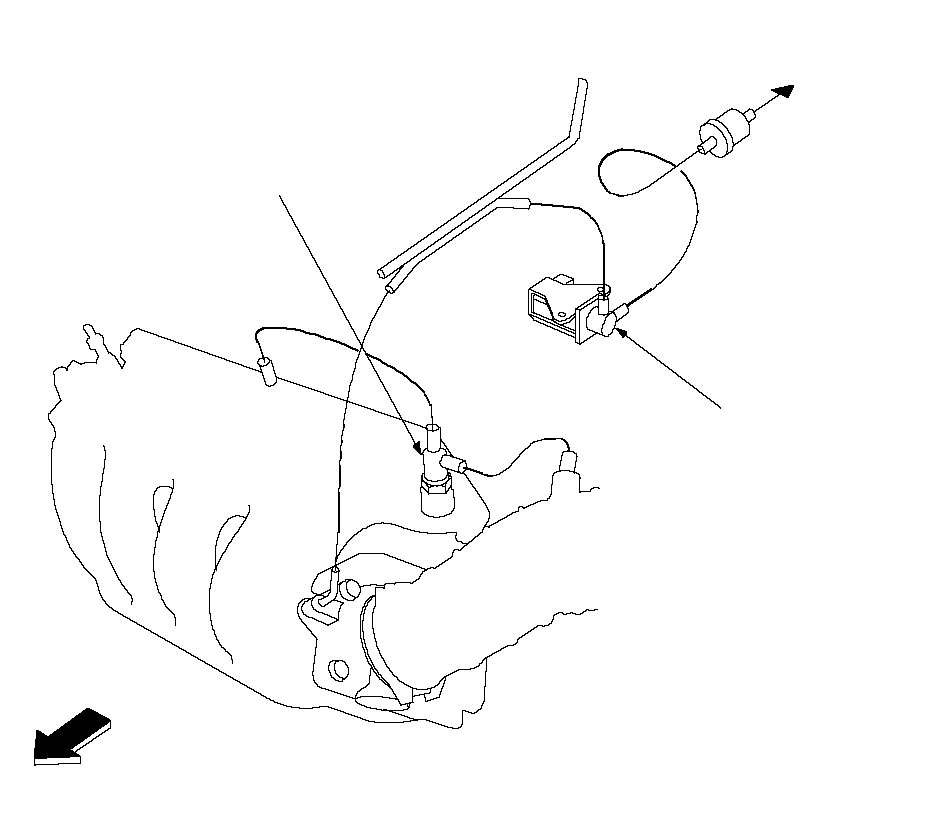 To
ToEVAPORATIVE
EMISSION (EVAP)
CANISTERINTAKE AIR
BYPASS CONTROL
THERMAL VALVE
(With TWC model)EVAPORATIVE EMISSION
(EVAP) CANISTER PURGE VALVEFRONT OF
VEHICLE
Vacuum Distribution
K24A3 engine:
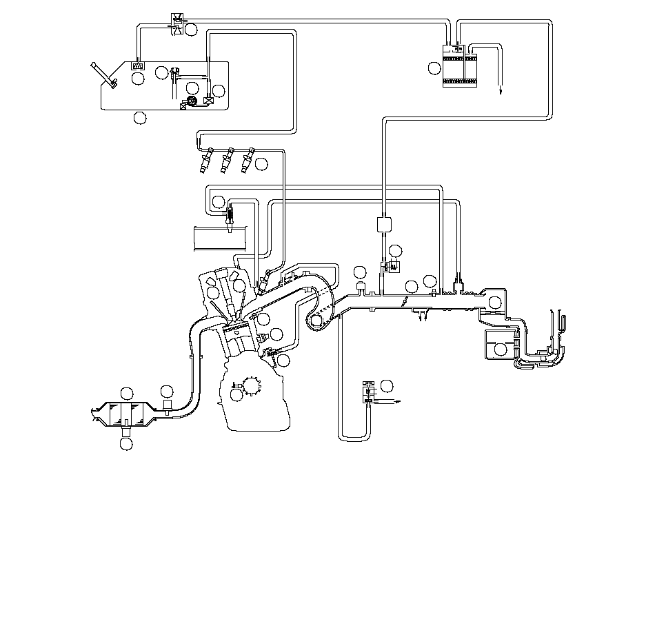 3525To ENGINE MOUNT1061947248922ENGINE
COOLANT1314151611231221ATMOSPHERE20181712ENGINE
COOLANTAIR FUEL RATIO (A/F) SENSOR (SENSOR 1)SECONDARY HEATED OXYGEN SENSOR
(SECONDARY HO2S) (SENSOR 2)MANIFOLD ABSOLUTE PRESSURE (MAP) SENSORENGINE COOLANT TEMPERATURE (ECT) SENSORINTAKE AIR TEMPERATURE (IAT) SENSORCRANKSHAFT POSITION (CKP) SENSORKNOCK SENSORCAMSHAFT POSITION (CMP) SENSOR BCAMSHAFT POSITION (CMP) SENSOR ATHROTTLE BODYINJECTORFUEL FILTERFUEL PRESSURE REGULATORFUEL PUMPFUEL TANKRESONATORPOSITIVE CRANKCASE VENTILATION (PCV) VALVETHREE WAY CATALYTIC CONVERTEREVAPORATIVE EMISSION (EVAP) CANISTER
PURGE VALVEENGINE MOUNT CONTROL SOLENOID VALVEINTAKE AIR BYPASS CONTROL THERMAL VALVE(1)(2)(3)(4)(5)(6)(7)(8)(9)(10)(11)(12)(13)(14)(15)(16)(18)(19)(20)(21)(22)(23)(24)(25)FUEL TANK VAPOR/LIQUID SEPARATION VALVE(17)EVAPORATIVE EMISSION (EVAP) CANISTEREVAPORATIVE EMISSION (EVAP) TWO WAY VALVEAIR CLEANER
Vacuum Distribution (cont'd)
K20A6 engine:
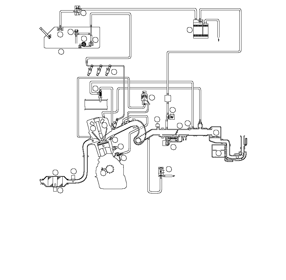 351027To ENGINE MOUNT1162147268924ENGINE
COOLANT1415161712251323ATMOSPHERE2022121918ENGINE
COOLANTAIR FUEL RATIO (A/F) SENSOR (SENSOR 1)SECONDARY HEATED OXYGEN SENSOR
(SECONDARY HO2S) (SENSOR 2)MANIFOLD ABSOLUTE PRESSURE (MAP) SENSORENGINE COOLANT TEMPERATURE (ECT) SENSORINTAKE AIR TEMPERATURE (IAT) SENSORCRANKSHAFT POSITION (CKP) SENSORKNOCK SENSORCAMSHAFT POSITION (CMP) SENSOR BCAMSHAFT POSITION (CMP) SENSOR ATHROTTLE BODYINJECTORFUEL FILTERFUEL PRESSURE REGULATORFUEL PUMPFUEL TANKRESONATORPOSITIVE CRANKCASE VENTILATION (PCV) VALVETHREE WAY CATALYTIC CONVERTEREVAPORATIVE EMISSION (EVAP) CANISTER
PURGE VALVEENGINE MOUNT CONTROL SOLENOID VALVEINTAKE AIR BYPASS CONTROL THERMAL VALVE(1)(2)(3)(4)(5)(6)(7)(8)(9)(10)(11)(12)(13)(14)(15)(16)(18)(19)(20)(21)(22)(23)(24)(25)FUEL TANK VAPOR/LIQUID SEPARATION VALVE(17)EVAPORATIVE EMISSION (EVAP) CANISTEREVAPORATIVE EMISSION (EVAP) TWO WAY VALVEAIR CLEANERIDLE AIR CONTROL (IAC) VALVEEXHAUST GAS RECIRCULATION (EGR) VALVE and
POSITION SENSOR(26)(27)
PGM-FI System
The Programmed Fuel Injection (PGM-FI) system is a sequential multiport fuel injection system.
Air Conditioning (A/C) Compressor Clutch Relay
When the ECM/PCM receives a demand for cooling from the A/C system, it delays the compressor from being energized, and enriches the mixture to assure smooth transition to the A/C mode.Air Fuel Ratio (A/F) Sensor
The A/F Sensor operates over a wide air/fuel range. The A/F Sensor is installed upstream of the TWC, and sends signals to the ECM/PCM which varies the duration of fuel injection accordingly.
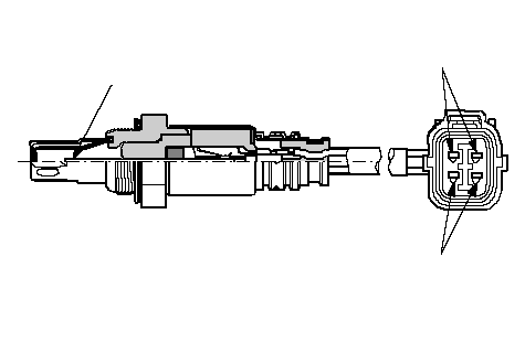 SENSOR
TERMINALSHEATER
TERMINALSZIRCONIA
ELEMENT
Barometric Pressure (BARO) Sensor
The BARO sensor is inside the ECM/PCM. It converts atmospheric pressure into a voltage signal that modifies the basic duration of the fuel injection discharge.Camshaft Position (CMP) Sensor B
CMP sensor B detects the position of the No. 1 cylinder as a reference for sequential fuel injection to each cylinder.
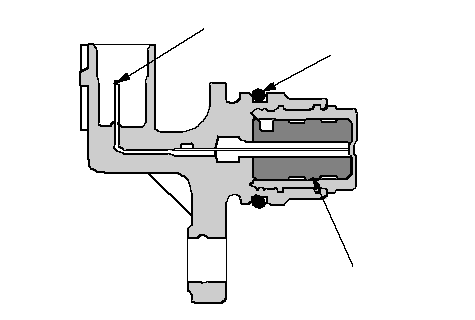 O-RINGMAGNETTERMINAL
Countershaft Speed Sensor
This sensor detects countershaft speed.
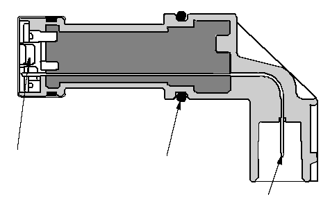 MAGNETO-RINGTERMINAL
Crankshaft Position (CKP) Sensor
The CKP sensor detects crankshaft speed and is used by the ECM/PCM to determine ignition timing and timing for fuel injection of each cylinder as well as detecting engine misfire.
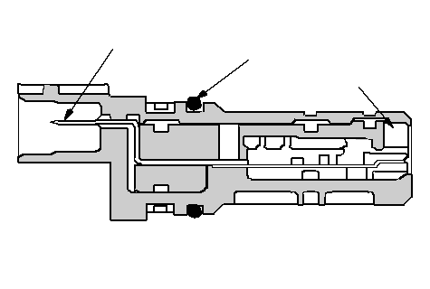 O-RINGMAGNETTERMINAL
Engine Coolant Temperature (ECT) Sensor
The ECT sensor is a temperature dependent resistor (thermistor). The resistance of the thermistor decreases as the engine coolant temperature increases.
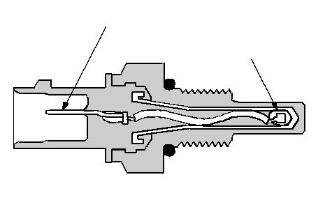 THERMISTORTERMINAL
Ignition Timing Control
The ECM/PCM contains the memory for basic ignition timing at various engine speeds and manifold absolute pressure. It also adjusts the timing according to engine coolant temperature and intake air temperature.Injector Timing and Duration
The ECM/PCM contains the memory for basic discharge duration at various engine speeds and manifold pressures. The basic discharge duration, after being read out from the memory, is further modified by signals sent from various sensors to obtain the final discharge duration.By monitoring long term fuel trim, the ECM/PCM detects long term malfunctions in the fuel system and sets a diagnostic trouble code (DTC).
Intake Air Temperature (IAT) Sensor
The IAT sensor is a temperature dependent resistor (thermistor). The resistance of the thermistor decreases as the intake air temperature increases.
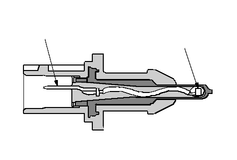 TERMINALTHERMISTOR
Knock Sensor
The knock control system adjusts the ignition timing to minimize knock.
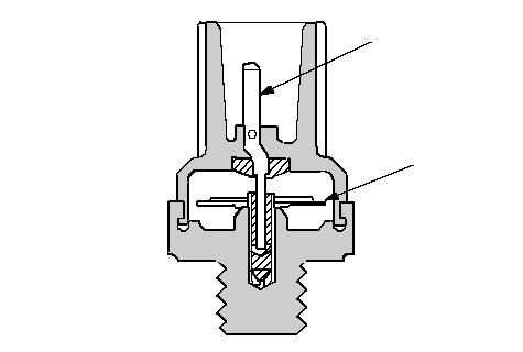 TERMINALPIEZO
CERAMIC
ELEMENT
Malfunction Indicator Lamp (MIL) Indication
If the vehicle's battery has been disconnected or gone dead, if the DTCs have been cleared, or if the ECM/PCM has been reset, these codes are reset. In some states, part of the emissions testing is to make sure these codes are set to complete. If all of them are not set to complete, the vehicle may fail the test, or the test cannot be finished.Manifold Absolute Pressure (MAP) Sensor
The MAP sensor converts manifold absolute pressure into electrical signals to the ECM/PCM.
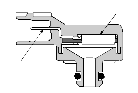 TERMINALSENSOR UNIT
Secondary Heated Oxygen Sensor (Secondary HO2S)
The secondary HO2S detects the oxygen content in the exhaust gas downstream of the three way catalytic converter (TWC), and sends signals to the ECM/PCM which varies the duration of fuel injection accordingly. To stabilize its output, the sensor has an internal heater. The ECM/PCM compares the HO2S output with the A/F sensor output to determine catalyst efficiency. The secondary HO2S is located on the TWC.
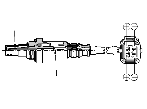 SENSOR
TERMINALSHEATER
TERMINALSZIRCONIA
ELEMENTHEATER
Throttle Position (TP) Sensor (K20A6 engine)
The TP sensor is a potentiometer connected to the throttle valve shaft. As the throttle position changes, the sensor varies the signal voltage to the ECM/PCM. The TP sensor is not available separately from the throttle body.
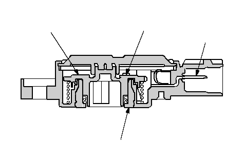 ELEMENTBRUSH HOLDERTERMINALBRUSH
Electronic Throttle Control System (K24A3 engine)
The throttle is electronically controlled by the electronic throttle control system. Refer to the System Diagram to see the functional layout of the system.
Idle control: When the engine is idling, the ECM/PCM controls the throttle actuator to maintain the proper idle speed according to engine loads.
Acceleration control: When the accelerator pedal is pressed, the ECM/PCM opens the throttle valve depending on the accelerator pedal position (APP) sensor signal.
Cruise control: The ECM/PCM controls the throttle actuator to maintain set speed when the cruise control is operating. The throttle actuator takes the place of the cruise control actuator.
Accelerator Pedal Position (APP) Sensor
As the accelerator pedal position changes, the sensor varies the signal voltage to the ECM/PCM.
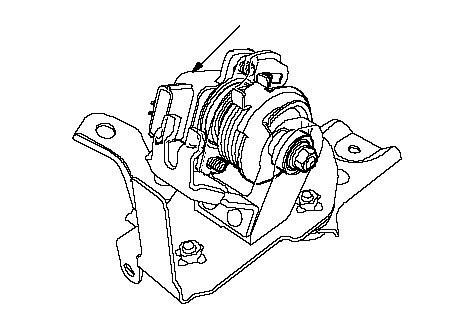 APP SENSOR
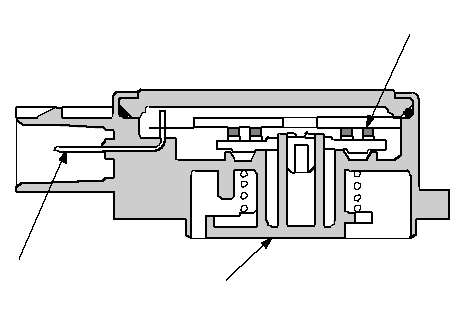 BRUSHLEVERTERMINAL
Throttle Body
The throttle body is a single-barrel side draft type. The lower portion of the throttle valve is heated by engine coolant from the cylinder head to prevent icing of the throttle plate.
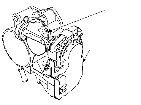 THROTTLE VALVETHROTTLE POSITION
(TP) SENSOR and
THROTTLE ACTUATOR
VTEC/VTC
- The i-VTEC has a VTC (Variable Valve Timing Control) mechanism on the intake camshaft in addition to the usual VTEC.
This mechanism improves fuel efficiency and reduces exhaust emissions at all levels of engine speed, vehicle speed, and engine load. - The VTEC mechanism changes the valve lift and timing by using more than one cam profile.
- The VTC changes the phase of the intake camshaft via oil pressure. It changes the intake valve timing continuously.
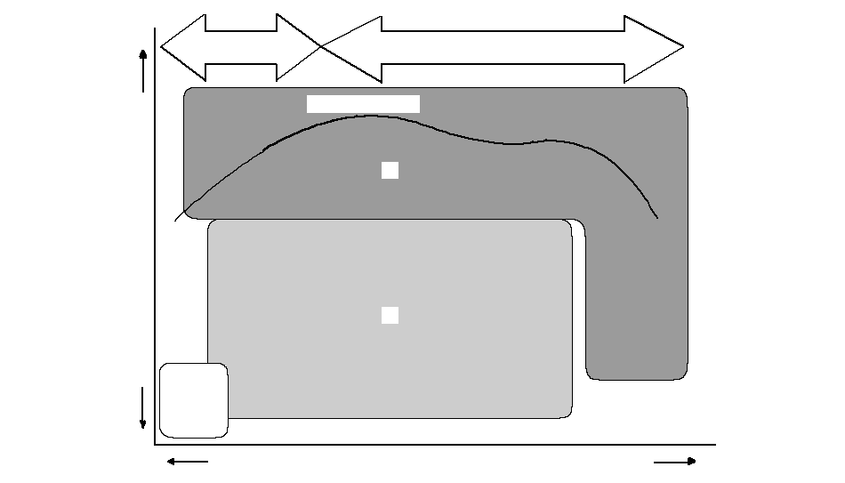 LOW SPEED CAMHIGH SPEED CAMHIGHENGINE SPEEDHIGHLOWLOWENGINE
LOAD(1)(3)(2)TORQUE CURVE
| Driving Condition | VTC Control | Description |
|---|---|---|
| (1) Light-load | Base Position | Cam angle is retarded to reduce the entry of exhaust gas into the intake port. |
| (2) Medium/high-load | Advance Control | To reduce pumping loss, the intake valve is closed quickly to help reduce the entry of air/fuel mixture into the intake port and improve the charging effect. |
| (3) High speed | Advance-Base Position | Cam phase angle is controlled for optimum valve timing and maximum engine power. |
VTC system
- The VTC system makes continuous intake valve timing changes based on operating conditions.
- Intake valve timing is optimized to allow the engine to produce maximum power.
- Cam angle is advanced to obtain the EGR effect and reduce pumping loss. The intake valve is closed quickly to reduce the entry of the air/fuel mixture into the intake port and improve the charging effect.
- The system reduces the cam advance at idle, stabilizes combustion, and reduces engine speed.
- If a malfunction occurs, the VTC system control is disabled and the valve timing is fixed at the fully retarded position.
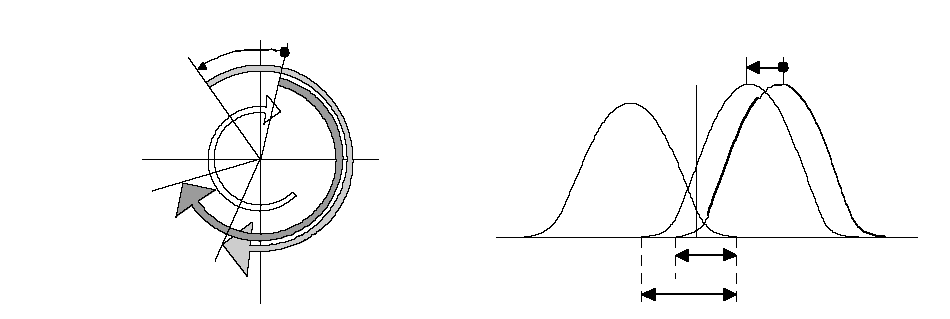 MAXIMUM VTC ADVANCE 25°TDCEXIN 1IN 2EXIN 2IN 1MAXIMUM VTC ADVANCE 25°SHORT OVERLAPLONG OVERLAP
VTEC system
- The VTEC system changes the cam profile to correspond to the engine speed. It maximizes torque at low engine speed and output at high engine speed.
- The low lift cam is used at low engine speeds, and the high lift cam is used at high engine speeds.
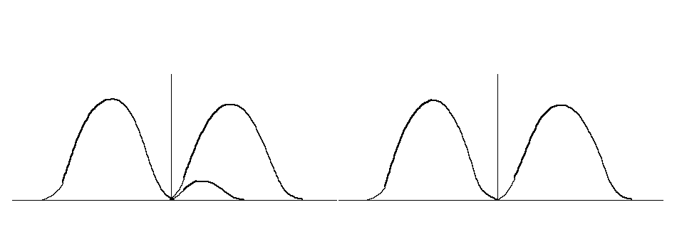 LOW SPEED VALVE TIMINGHIGH SPEED VALVE TIMINGEXINEXIN
VTEC/VTC
System Diagram
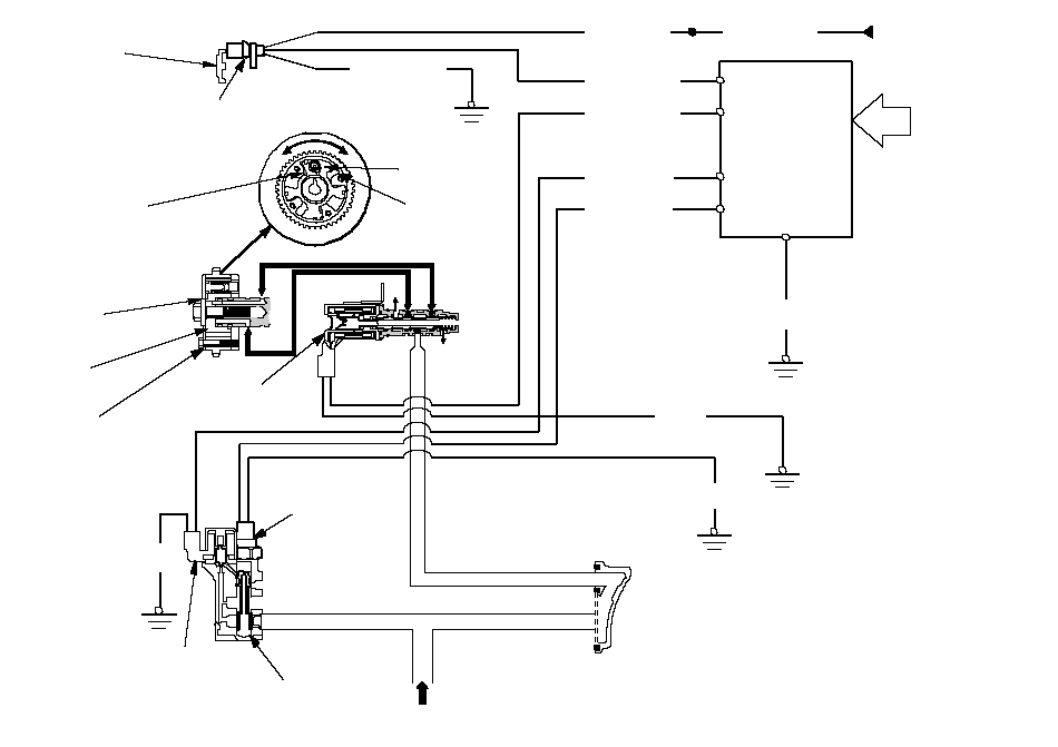 VTC
VTCRETARD
CHAMBERFrom No.18
ACG (15A) fuseVARIOUS
SENSORSECM/PCMCMP SENSOR AINTAKE
CAMSHAFTVTC
ADVANCE
CHAMBERADVANCERETARDVANEVTC ACTUATORVANEHOUSINGDRAINDRAINFrom
OIL PUMPVTC OIL CONTROL
SOLENOID VALVESPOOL
VALVEVTEC
SOLENOID
VALVEVTC OIL
PRESSURE
SWITCHBLKBLKGRN/YELBLU/BLKBLU/YELBLU/WHTBLU/WHTBLK/REDBRN/YELBLKBRN/YELVTC STRAINER
Camshaft Position (CMP) Sensor A
This sensor detects camshaft angle position for the VTC system.
 MAGNETO-RINGTERMINAL
Idle Control System
When the engine is cold, the A/C compressor is on, the transmission is in gear, the brake pedal is pressed, the power steering load is high, or the alternator is charging, the ECM/PCM controls current to the idle air control (IAC) valve to maintain the correct idle speed. Refer to the System Diagram to see the functional layout of the system.
Brake Pedal Position Switch
The brake pedal position switch signals the ECM/PCM when the brake pedal is pressed.Idle Air Control (IAC) Valve (K20A6 engine)
To maintain proper idle speed, the IAC valve changes the amount of air bypassing the throttle body in response to an electrical signal from the ECM/PCM.
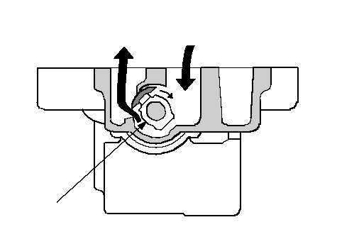 IAC VALVETo INTAKE
MANIFOLDFrom AIR
CLEANER
Power Steering Pressure (PSP) Switch
The PSP switch signals the ECM/PCM when the power steering load is high.Fuel Supply System
Fuel Cut-off Control
During deceleration with the throttle valve closed, current to the injectors is cut off to improve fuel economy at engine speeds over 1,000 rpm (min-1)(M/T: 1,000 rpm (min-1)). Fuel cut-off control also occurs when the engine speed exceeds 7,300 rpm (min-1)
(K20A6 engine: 6,900 rpm (min-1)), regardless of the position of the throttle valve, to protect the engine from over-revving. When the vehicle is stopped, the ECM/PCM cuts the fuel at engine speeds over 5,000 rpm (min-1) (M/T: 4,500 rpm (min-1)).
Fuel Pump Control
When the ignition is turned on, the ECM/PCM grounds the PGM-FI main relay which feeds current to the fuel pump for 2 seconds to pressurize the fuel system. With the engine running, the ECM/PCM grounds the PGM-FI main relay and feeds current to the fuel pump. When the engine is not running and the ignition is on, the ECM/PCM cuts ground to the PGM-FI main relay which cuts current to the fuel pump.PGM-FI Main Relay 1 and 2
The PGM-FI relay consists of two separate relays. PGM-FI main relay 1 (FI MAIN) is energized whenever the ignition switch is ON (II) to supply battery voltage to the ECM/PCM, power to the injectors, and power for PGM-FI main relay 2 (FUEL PUMP). PGM-FI main relay 2 is energized to supply power to the fuel pump for 2 seconds when the ignition switch is turned ON (II), and when the engine is cranking or running.Intake Air System
Refer to the System Diagram to see the functional layout of the system.
Intake Air Bypass Control Thermal Valve (with TWC model)
When the engine is cold, the intake air bypass control thermal valve sends air to the injector.
The amount of air is regulated by engine coolant temperature. Once the engine is hot, the intake air bypass control thermal valve closes, stopping air to the injector.
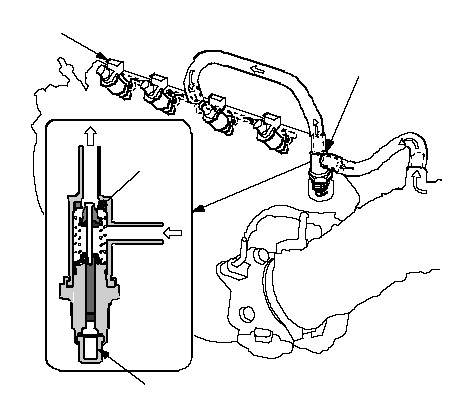 OUTVALVEINWAX ELEMENTINJECTORINTAKE AIR
BYPASS CONTROL
THERMAL VALVE
Throttle Body (K20A6 engine)
The throttle body is a single-barrel side draft type. The lower portion of the idle air control (IAC) valve is heated by engine coolant from the cylinder head to prevent icing of the throttle plate.
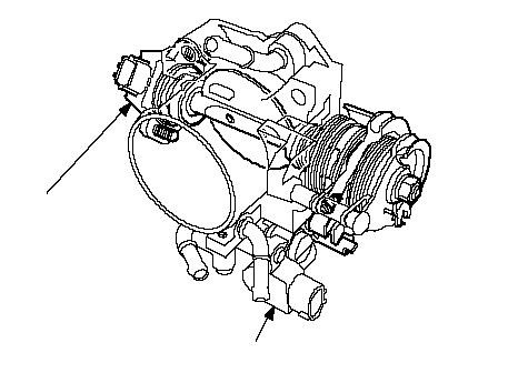 TP SENSORIAC VALVE
Catalytic Converter System (with TWC model)
Three Way Catalytic Converter (TWC)
The TWC converts hydrocarbons (HC), carbon monoxide (CO), and oxides of nitrogen (NOx) in the exhaust gas to carbon dioxide (CO2), nitrogen (N2), and water vapor.
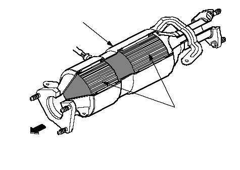 THREE WAY
CATALYSTFRONT OF
VEHICLEHOUSING
Positive Crankcase Ventilation (PCV) System
The PCV valve prevents blow-by gasses from escaping into the atmosphere by venting them into the intake manifold.
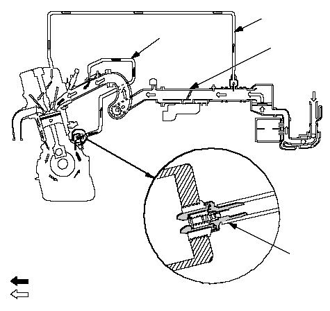 PCV
PCVVALVEPCV
HOSE: BLOW-BY VAPOR: FRESH AIRBREATHER
PIPEINTAKE
MANIFOLD
Evaporative Emission (EVAP) Control System
Refer to the System Diagram to see the functional layout of the system.
EVAP Canister
The EVAP canister temporarily stores fuel vapor from the fuel tank until it can be purged from the EVAP canister into the engine and burned.EVAP Canister Purge Valve
When the engine coolant temperature is below 65°C (149°F), the ECM/PCM turns off the EVAP canister purge valve which cuts vacuum to the EVAP canister.Idle Control System Diagram (K20A6 engine)
The idle speed of the engine is controlled by the idle air control (IAC) valve:
- After the engine starts, the IAC valve opens for a certain amount of time. The amount of air is increased to raise the idle speed.
- When the engine coolant temperature is low, the IAC valve is opened to obtain the proper fast idle speed. The amount of bypassed air is controlled in relation to engine coolant temperature.
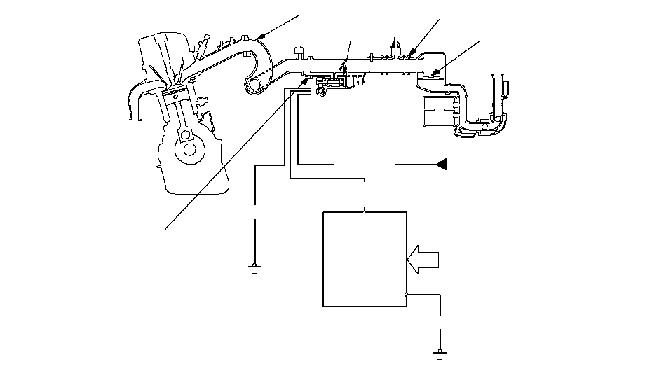 ENGINE
COOLANTVARIOUS
SENSORSFrom
PGM-FI
MAIN
RELAYBLK/
REDBLKBLKECM/PCMYEL/BLKTHROTTLE BODYINTAKE MANIFOLDIAC VALVEINTAKE AIR DUCTAIR CLEANER
Intake Air System Diagram
This system supplies air for engine needs. A resonator in the intake air duct provides additional silencing as air is drawn into the system.
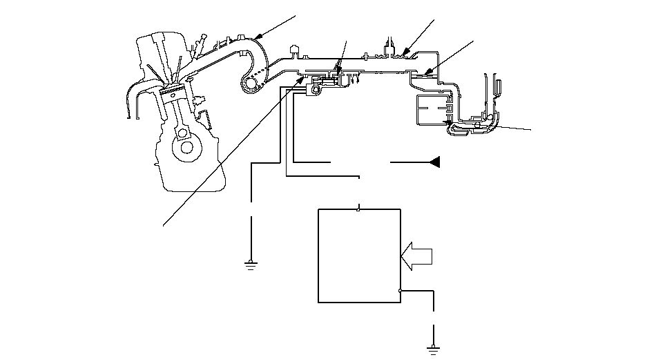 ENGINE
COOLANTVARIOUS
SENSORSFrom
PGM-FI
MAIN
RELAYBLK/
REDBLKBLKECM/PCMYEL/BLKTHROTTLE BODYINTAKE MANIFOLDIAC VALVEINTAKE AIR DUCTAIR CLEANERRESONATOR
Electronic Throttle Control System Diagram (K24A3 engine)
The electronic throttle control system consists of the throttle actuator, throttle position (TP) sensor, accelator pedal position (APP) sensor, throttle actuator control module, and the ECM/PCM. The throttle is electronically controlled by this system.
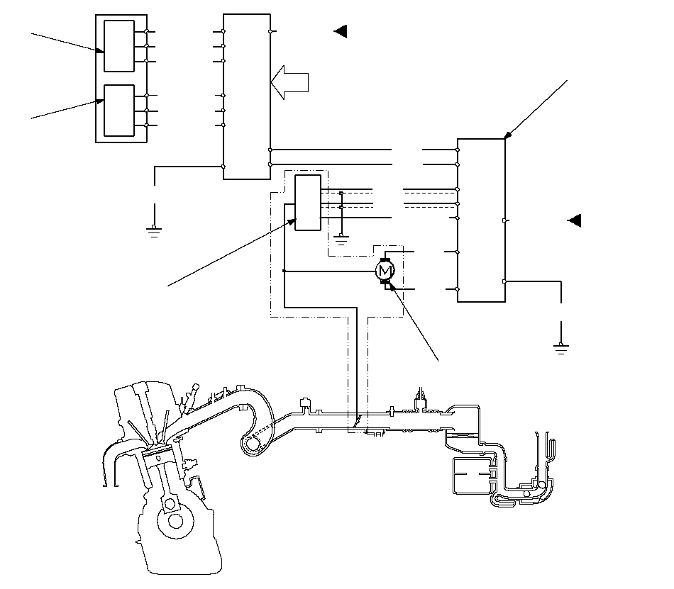 YEL/REDRED/BLUYEL/BLURED/YELGRN/YELGRNBLURED/BLKBLUGRNBLKBLKFrom THROTTLE
ACTUATOR
CONTROL MODULE
RELAYVARIOUS
SENSORSFrom
THROTTLE
ACTUATOR
CONTORL
MODULE
RELAYTP SENSOR A/BTHROTTLE ACTUATORECM/
PCMAPP
SENSOR BTHROTTLE
ACTUATOR
CONTORL
MODULEGRNBLUYEL/GRNGRN/WHTBRN/YELAPP
SENSOR A
Exhaust Gas Recirculation (EGR) System Diagram (K20A6 engine)
The EGR system reduces oxides of nitrogen (NOx) emissions by recirculating exhaust gas through the EGR valve and the intake manifold into the combustion chambers. The ECM/PCM memory includes the ideal EGR valve position for varying operating conditions.
The EGR valve position sensor detects the amount of EGR valve lift and sends it to the ECM/PCM. The ECM/PCM then compares it with the ideal lift in its memory (based on signals sent from other sensors). If there is any difference between the two, the ECM/PCM cuts current to the EGR valve.
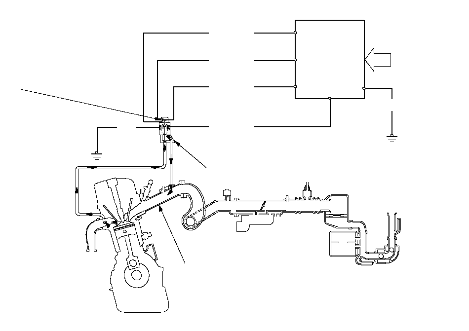 INTAKE MANIFOLDEGR VALVEEGR VALVE
POSITION
SENSORVARIOUS
SENSORSYEL/BLUGRN/YELWHT/BLKBLU/REDBLKBLKECM/PCM
Evaporative Emission (EVAP) Control Diagram
The EVAP controls minimize the amount of fuel vapor escaping to the atmosphere. Vapor from the fuel tank is temporarily stored in the EVAP canister until it can be purged from the canister into the engine and burned.
- The EVAP canister is purged by drawing fresh air through it and into a port on the intake manifold.
The purging vacuum is controlled by the EVAP canister purge valve, which operates whenever engine coolant temperature is above 65°C (149°F).
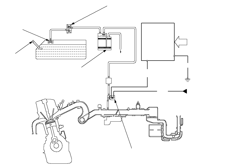 ATMOSPHEREFUEL TANKFUEL TANK
VAPOR/LIQUID
SEPARATION VALVEEVAP
TWO WAY VALVEFUEL FILL CAPECM/PCMVARIOUS
SENSORSBLK/
REDBLKYEL/
BLUFrom
No. 18 ACG
(15 A)
fuseEVAP
CANISTEREVAP CANISTER
PURGE VALVE
ECM/PCM Circuit Diagram
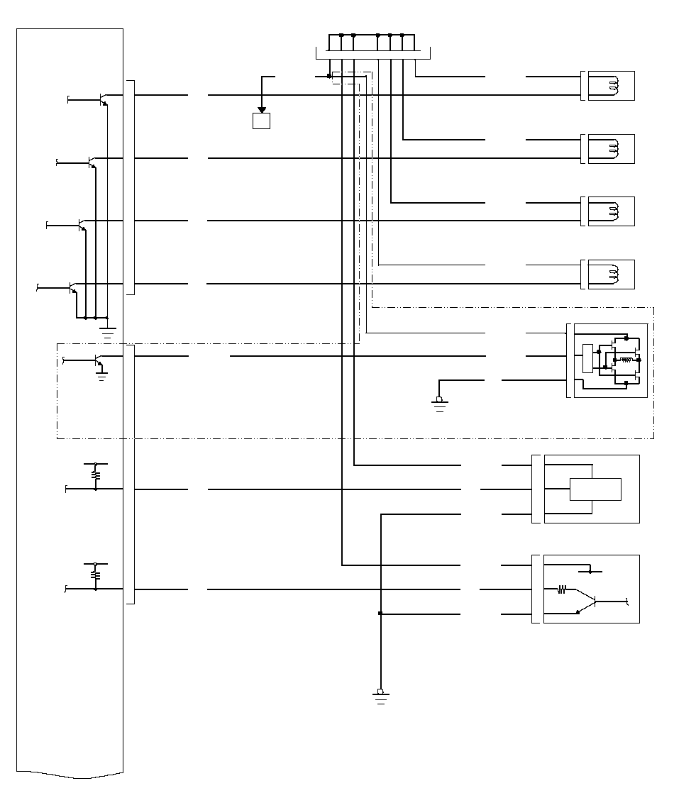 No. 1 INJECTORNo. 2 INJECTORNo. 3 INJECTORNo. 4 INJECTORIAC VALVEBLKYEL/BLKYEL/BLKYEL/BLKYEL/BLKYEL/BLK24P JUNCTION
CONNECTOR1CKP SENSORCMP SENSOR BYEL/BLKYEL/BLKBRN/YELBRN/YELG101G101242223181920212121212231312123BLUGRNBLK/REDYELBLK/REDBLUREDBRNAYEL/BLKBLUGRN*7: K20A6 engineA12B2B4B3B5A6A7IACVINJ4INJ2INJ3INJ1CMPBCKPECM/PCM*7
ECM/PCM Circuit Diagram (cont'd)
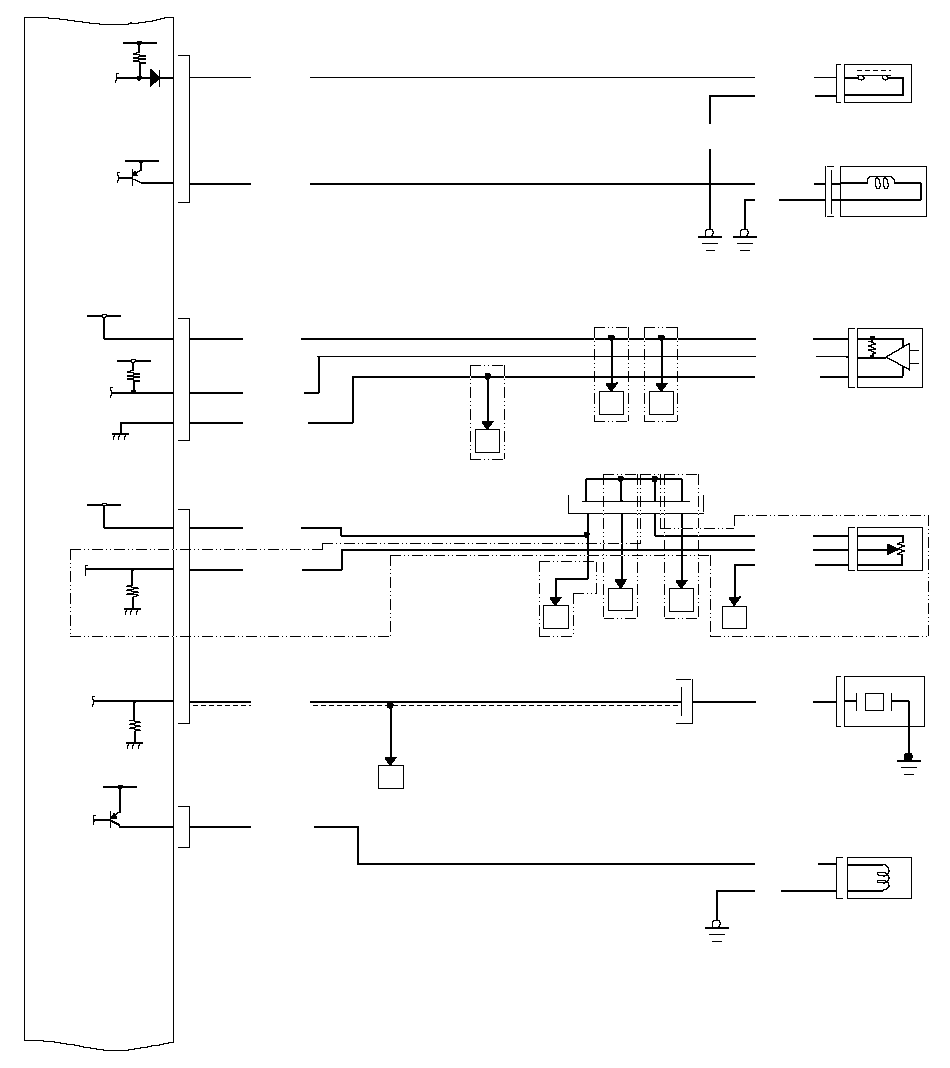 B11BLU/BLKBRN/YELVTEC OIL
 PRESSURE
SWITCHMAP SENSORA21A30A24YEL/REDGRN/WHTTP SENSORA29YEL/BLUGRN/YELRED/BLKB1BLU/WHTBA20YEL/BLUA1RED/BLUKNOCK SENSORRED/BLK113GRN/REDRED/BLU6P CONNECTORVTC OIL CONTROL
SOLENOID VALVEFG101B6GRN/YEL*1VTPSWVTSVCC1MAPSG1VCC2TPSKSVTCBLU/WHT21BLKG10115YEL/REDGRN/WHTGRN/REDH2124P JUNCTION
CONNECTORDG*1989623G101BRN/
YELBLU/BLKVTEC SOLENOID
VALVE1BLKGRN/YEL22*3*3CWE*7*3*7*1: A/T
*3: K24A3 engine
*7: K20A6 engine
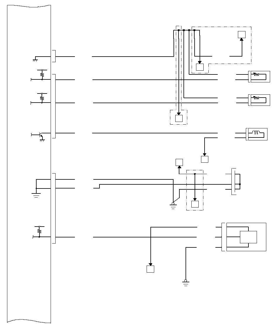 IAT SENSORECT SENSORA23B17B8RED/WHTRED/YELGRN/YELGRN/YELGRN/YELRED/WHTRED/YELJBLK/YELB15BLU/YELENGINE MOUNT
CONTROL
SOLENOID VALVE224P JUNCTION
CONNECTOR12A8A9HBRN/YELBRN/YELBRN/YELBRN/YELG101BLU/WHTCMP SENSOR ABRN/YELBLK/YELKG1013A1912BLU/WHTSG2IATECTMCSLG1LG2CMPAFGRN/YELI*1MBLU/YEL110112112L*3*7*1: A/T
*3: K24A3 engine
*7: K20A6 engine
ECM/PCM Circuit Diagram (cont'd)
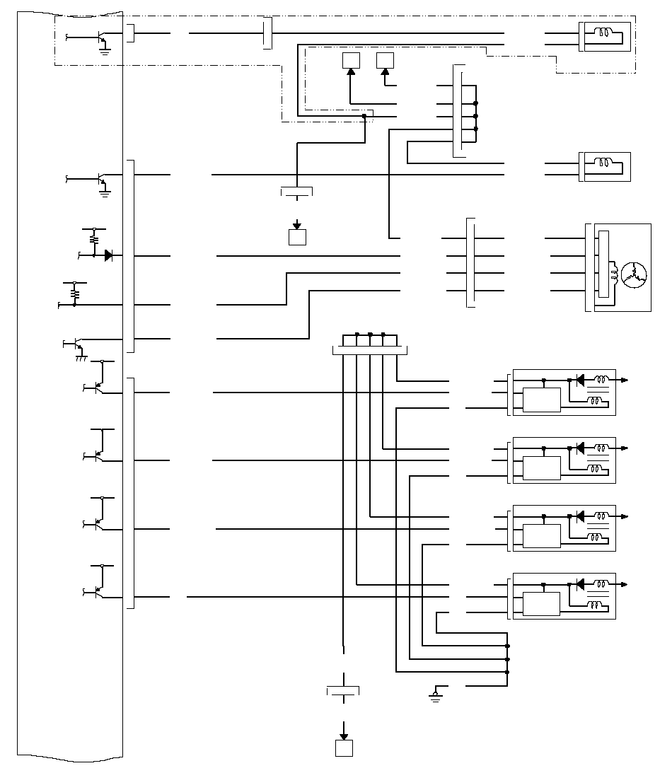 EVAP CANISTER
PURGE VALVEBLK/YELB21NBLK/YELBLK/YELNo. 1 IGNITION COILNo. 3 IGNITION COILA16A15A14G101BLKBLKBLK/WHTBLKICMTo
SPARK
PLUGICMTo
SPARK
PLUGICMTo
SPARK
PLUGNo. 2 IGNITION COIL17WHT/BLUBLU/REDNo. 4 IGNITION COILA13BLKICMTo
SPARK
PLUG24P JUNCTION
CONNECTOR24P JUNCTION
CONNECTORBLKOBLK/
WHTBLK/YELB10YEL/GRNBLK/WHTBLK/WHTBRNBLK/WHTWHT/BLUALTERNATOR113YEL/BLUBLK/YELJWHT/BLU6P CONNECTOR1B13WHT/REDWHT/REDWHT/GRNB18WHT/GRN12543BLK/
RED13P
CONNECTOR62342432BLK/YELWHT/BLUWHT/REDWHT/GRNPCSIGPLS1IGPLS2IGPLS3IGPLS4ALTLALTFALTCKWHT/BLUBLU/REDYEL/GRNBRNBLK/
WHT1313P
CONNECTOR1615141312312312312YEL/BLUREVERSE LOCK
SOLENOID VALVEGRN/BLK12BLK/YELE2RVSGRN1113P
CONNECTOR*5*5: K24A3 engine (M/T)
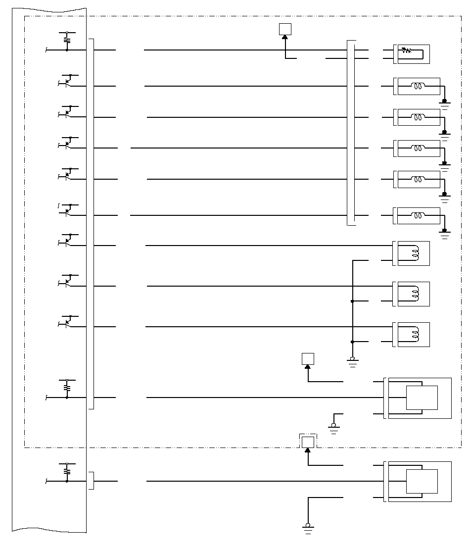 SHIFT SOLENOID
VALVE DRED/BLKC1BRN/WHTBLU/YELC15C7WHT/REDC19BLK/BLUA18A/T CLUTCH PRESSURE
CONTROL SOLENOID VALVE AA/T CLUTCH PRESSURE
CONTROL SOLENOID VALVE BA/T CLUTCH PRESSURE
CONTROL SOLENOID VALVE CMAINSHAFT
SPEED SENSORG101BRN/YELYEL/REDBCOUNTERSHAFT
SPEED SENSORYEL/BLUDBRN/YEL*1C3YELSHIFT SOLENOID
VALVE ERED1123G101LSALSBLSCNMNCSHEC14RED/YELC6BLU/BLKC4GRN/WHTATF TEMPERATURE
SENSORIWHTWHTSHIFT SOLENOID
VALVE ABLUSHIFT SOLENOID
VALVE BORNGRN/YEL8P CONNECTOR6ATFTSHASHBC2GRNSHIFT SOLENOID
VALVE CGRNSHCC5GRN/REDYELSHD21212BLKBLKBLKG101752183123*1: A/T
ECM/PCM Circuit Diagram (cont'd)
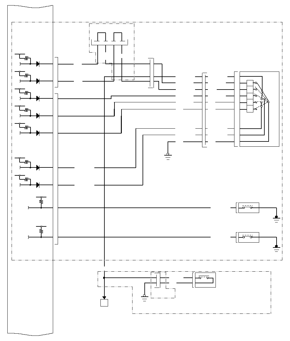 *2BLU/WHTRED/BLKBLU/BLKWHT/GRN1YEL/GRNBLKRED/WHTREDBLU/YEL109875263CLUTCH PEDAL
POSITION SWITCHPRNDTRANSMISSION
RANGE SWITCHD32ND CLUTCH
TRANSMISSION
FLUID
PRESSURE SWITCH3RD CLUTCH
TRANSMISSION
FLUID
PRESSURE SWITCH11BLU/REDBLU/WHT*1D6D5BLUGRNC17C20P28P JUNCTION
CONNECTORATPPATPRATPDATPNC9ATPD3C13C10OP2SWOP3SWC18BLU/YELATPFWDC12RED/WHTATPRVSBLU/
BLK109WHT1718Clutch pedal pressed:closed
Clutch pedal released:openBLKLT GRN23LT GRN13P
CONNECTOR1187G101BLU/WHTRED/BLKBLK/BLUWHT4PNKBLKWHT/REDBLUYEL/RED67283511010P CONNECTOR2P
CONNECTOR*812*9G451*1: A/T
*2: RHD model
*8: M/T
*9: LHD model
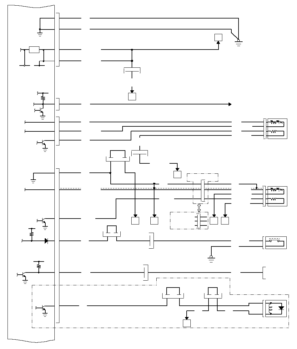 V216
V216(8)*2E16PSPSWG201BLKBLU/YEL5VA2A3IGP1IGP2G101A4A5PG2PG1AYEL/BLKQYEL/BLKBLKBLKYEL/
BLK1213P CONNECTORIMOCDE27REDTo IMMOBILIZER UNITE25NEP20P CONNECTORPSP SWITCH1220P CONNECTOR11(12)2GRYWHTE20SHO2SBLK/REDSECONDARY
HO2S
(SENSOR 2)BLKWHT/REDBLK/WHTGRN/BLKE21SO2SHTCLT GRNE3LG3BLKWHT/RED2BLKLT GRNWHT/BLKA/F
SENSOR
(SENSOR 1)RED/YEL2REDRED/YELREDGRN134AFS+A31AFS-A28GRNAFSHTCA10R1013P CONNECTORWHT/
BLK12P CONNECTOR9810134UT28P JUNCTION
CONNECTOR17
(9)BLU/WHTTEST
TACHOMETER
CONNECTOR*228P JUNCTION
CONNECTORS101121201924P
CONNECTOR*9*2*2WHT*1: A/T
*2: RHD model
*9: LHD modelT4
(9)*2E2SLS28P JUNCTION
CONNECTOR5
(8)2GRNSHIFT LOCK
SOLENOID*1*2252328P JUNCTION
CONNECTORYELYEL1
ECM/PCM Circuit Diagram (cont'd)
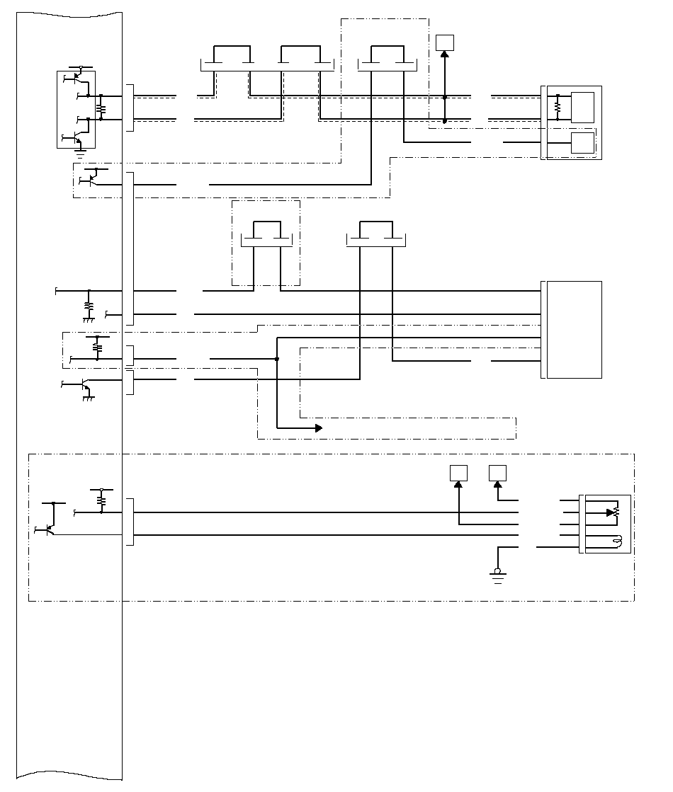 EGR VALVE
POSITION
SENSOREGR VALVEBLK6GRN/YEL2WHT/BLKB12EGRP1YEL/BLU3BLU/REDB16EGR4GMG101*7GAUGE ASSEMBLYWHT24RED23LT GRN2E11CANHE24CANLD10METINHLT GRNWHTREDTCRUISE CONTROL UNIT8141228P JUNCTION
CONNECTOR28P JUNCTION
CONNECTOR2827D12CCSD11ATCCFWDE26VSSOUTBLUORN
(BLU)PNK28P JUNCTION
CONNECTOR28P JUNCTION
CONNECTOR12
(27)11
(26)19
(20)18
(19)23
(21)22
(20)BLU*114LT BLUCRMTCLSD9*2*2*2*2*2*2*221
(18)20
(17)*2*2*9*6To CRUISE CLUTCH PEDAL POSITION SWITCH*4*5*4*1: A/T
*2: RHD model
*4: K20A6 engine (A/T)
*5: K24A3 engine (M/T)
*6: with cruise control
*7: K20A6 engine
*9: LHD model
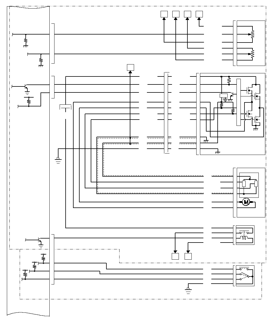 YEL/BLU1GRN/WHT6RED/YEL3GRN/YEL2ELRED/BLU4YEL/RED5A26APSAA25APSBAPP SENSORWCG101ORNWHTBRND2THROTTLE ACTIATOR
CONTROL MODULE
RELAYYXSHIFT LEVERBLK37821652BLUGRNBLUGRNTHROTTLE ACTUATOR
CONTROL MODULEL13P CONNECTORGRY3B19SEFDB20SEDF1179BLKGRNBLUBLK37513P CONNECTOR101218RED/BLKRED/BLUGRNBLURED/BLKRED/BLUGRNBLU421362YEL/GRNYEL/GRN12146GRNBLUGRNBLU1113RED/BLK4RED/BLUTP SENSORTHROTTLE
ACTUATORTHROTTLE BODYGRYPNKBRNYEL/BLKD15DBWRLYSMODED3SUPD9SDN2134G501GRNBLU*1*3*1: A/T
*3: K24A3 engine
ECM/PCM Circuit Diagram (cont'd)
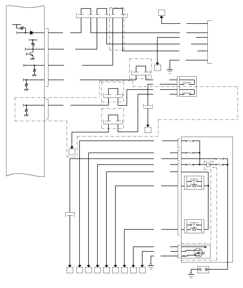 S28P JUNCTION CONNECTOR12
(16)14
(15)19
(23)21
(22)57ELDBATTERYG1RADIATOR
FAN RELAY132BLU/BLKBLK/REDBLK14GRN(1)(2)(3)(5)A/C CLUTCH
RELAY15RED9BLK/YEL6WHT/GRNREDBLK/REDE29BRNE23E30(4)UNDER-HOOD
FUSE/RELAY BOX:
(1) No. 23 +B IG MAIN (50A)
(2) No. 19 OPTION (40A)
(3) No. 8 FI ECU
(ECM/PCM) (15A)
(4) No. 13 HORN, STOP (20A)
(5) No. 22 BATTERY (100A)SCSK-LINEWENG201AKAJAIAHAGAFAEADLT BLURED
(WHT/RED)*2*2*2*2*2*9E22BKSWWHT/BLK28P JUNCTION
CONNECTOR*928P JUNCTION
CONNECTOR2824*9D8BKSWNCAA*39BRN16WHT/GRNLT BLU12RED
(WHT/RED)4BLKUNDER-HOOD
FUSE/RELAY BOX921WHTG451ZDATA LINK
CONNECTOR5BLK*2BRAKE PEDAL
POSITION SWITCHBrake pedal pressed:closed
Brake pedal released:openAB28P JUNCTION
CONNECTOR252WHT/BLK1RED3GRY
(BLK/RED)4*220P CONNECTOR
(7P CONNECTOR)12
(1)*2Brake pedal pressed:open
Brake pedal released:closed*91413AC5P
CONNECTOR1*2*2: RHD model
*3: K24A3 engine
*9: LHD modelBRNBRN
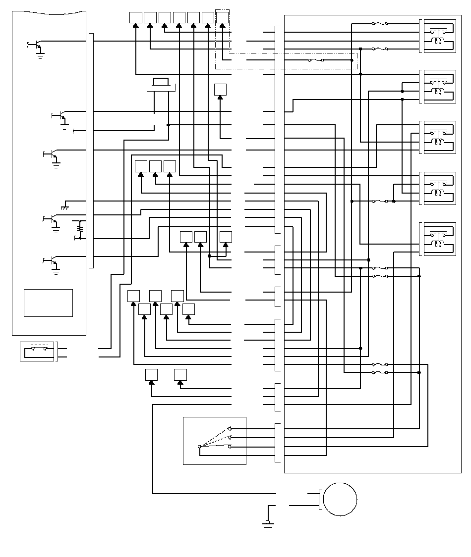 A/F SENSOR
RELAY (LAF)PGM-FI MAIN
RELAY 2
(FUEL PUMP)IGNITION COIL
RELAY
(IG COIL)STARTER
CUT RELAY
(ST CUT)(8)PGM-FI MAIN
RELAY 1
(FI MAIN)(9)(10)UNDER-DASH FUSE/RELAY BOX(7)(6)(11)RED/BLK1BLK/YEL38WHT3BLK/WHT31LT GRN32RED35BLK5BRN9BLU10GRN11RED21WHT/GRN10GRY
(BLK/RED)29BLK/RED2WHT1GRN15BLU/BLK13RED5BLK/RED2WHT/GRN10BLK/YEL7BLK/RED6GRN/BLK16YEL/GRN13UNDER-DASH
FUSE/RELAY BOX:
(6) No. 4 A/F SENSOR (10A)
(7) No. 23 IGP (7.5A)
(8) No. 2 IG COIL (15A)
(9) No. 18 ACG (15A)
(10) No. 19 FUEL PUMP (15A)
(11) No. 30 A/C (7.5A)
(12) No. 12 IG METER (7.5A)
(13) No. 1 THROTTLE ACTUATOR
CONTROL (15A)IGNITION SWITCHIG1ST+BIG26142E7MRLYE9IG1E17IMOFPRE4SG3E18ACCE15ELDE12FANCAEADACAIAHAFABVFUEL PUMPPYEL/GRN5BLK4G603E8AFSHTCRPBARO
SENSOR
(Built Into
the ECM/PCM)BLU/WHT36ORN2YEL/BLK30YEL/BLK8ZNORQYU28P JUNCTION
CONNECTORBLK/
YEL19
(1)17
(2)X16PNK(13)YEL/BLK4*2*2AKAJAGINERTIA SWITCH31YEL/BLKBLK/YEL*2AA(12)YELT33*3*2: RHD model
*3: K24A3 engine
ECM/PCM Circuit Diagram (cont'd)
LHD model:
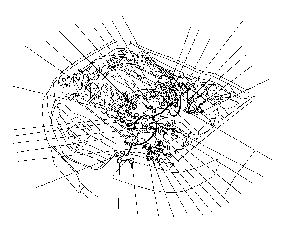 10234657891161719182011121413152627292830212224232531323433ENGINE
 WIRE HARNESSENGINE COMPARTMENT
WIRE HARNESS
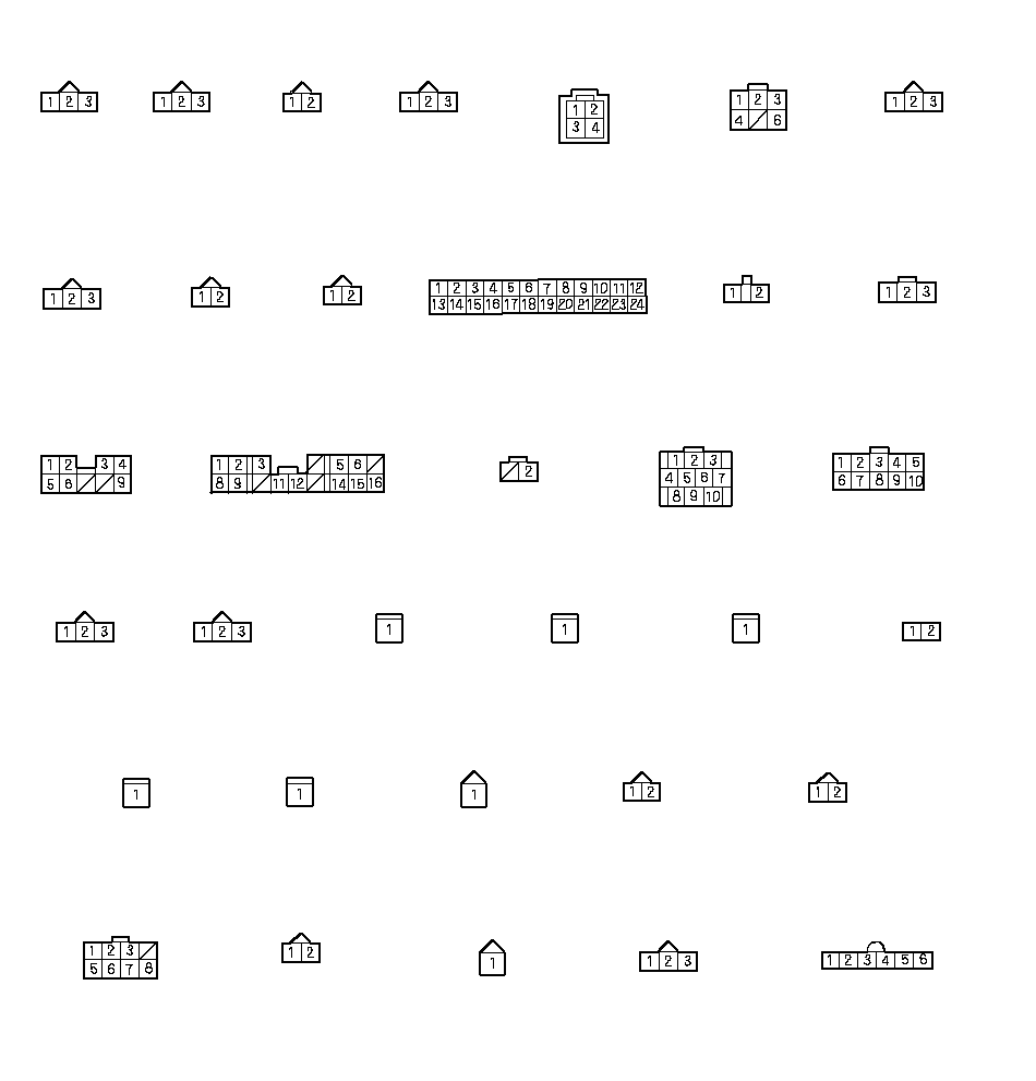 TRANSMISSION
RANGE SWITCH
(18) (A/T)MAP SENSOR
(1)TP SENSOR
(2)
(K20A6 engine)IAT
SENSOR
(3)COUNTERSHAFT
SPEED SENSOR
(4) (M/T)A/F SENSOR
(SENSOR 1)
(5)CMP SENSOR A
(7)CMP SENSOR B
(8)EVAP CANISTER
PURGE VALVE
(9)ECT
SENSOR
(10)EGR VALVE
(6)24P JUNCTION CONNECTOR(11)UNDER-HOOD
FUSE/RELAY
BOX (12)ELD(13)UNDER-HOOD
FUSE/RELAY
BOX (14)UNDER-HOOD
FUSE/RELAY
BOX (15)TEST
TACHOMETER
CONNECTOR
(16)10P CONNECTOR
(17) (A/T)SHIFT CONTROL
SOLENOID VALVE A
(25) (A/T)SHIFT CONTROL
SOLENOID VALVE C
(21) (A/T)SHIFT CONTROL
SOLENOID VALVE D
(26) (A/T)3RD CLUTCH
TRANSMISSION
FLUID
PRESSURE SWITCH
(27) (A/T)8P CONNECTOR
(30) (A/T)A/T CLUTCH
PRESSURE CONTROL
SOLENOID VALVE B
(28) (A/T)A/T CLUTCH
PRESSURE CONTROL
SOLENOID VALVE C
(29) (A/T)2ND CLUTCH
TRANSMISSION
FLUID
PRESSURE SWITCH
(32) (A/T)IAC VALVE
(33)
(K20A6 engine)MAINSHAFT
SPEED SENSOR
(19)COUNTERSHAFT
SPEED SENSOR
(20) (A/T)SHIFT CONTROL
SOLENOID VALVE E
(23) (A/T)ATF
TEMPERATURE
SENSOR
(24) (A/T) A/T CLUTCH
PRESSURE CONTROL
SOLENOID VALVE A
(31) (A/T)SHIFT CONTROL
SOLENOID VALVE B
(22) (A/T)THROTTLE BODY
(34)
(K24A3 engine)NOTE:
· Connector with male terminals (double outline) : view from terminal side
· Connector with female terminals (single outline) : view from wire side
ECM/PCM Circuit Diagram (cont'd)
LHD model:
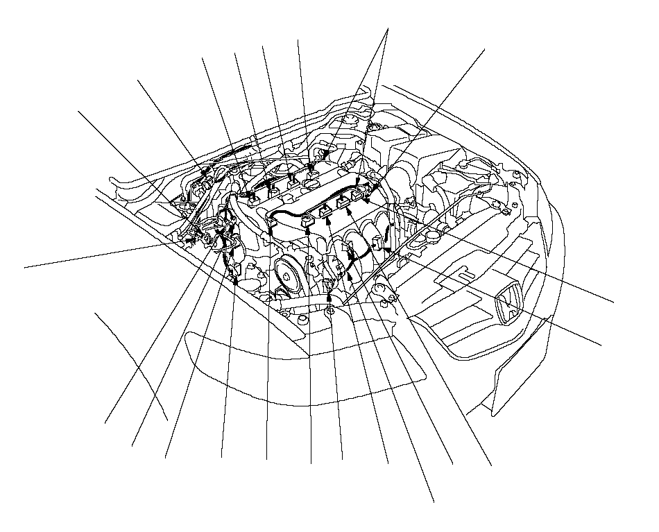 102346578911617181112141315ENGINE COMPARTMENT
WIRE HARNESSENGINE WIRE HARNESSG101STARTER SUBHARNESS
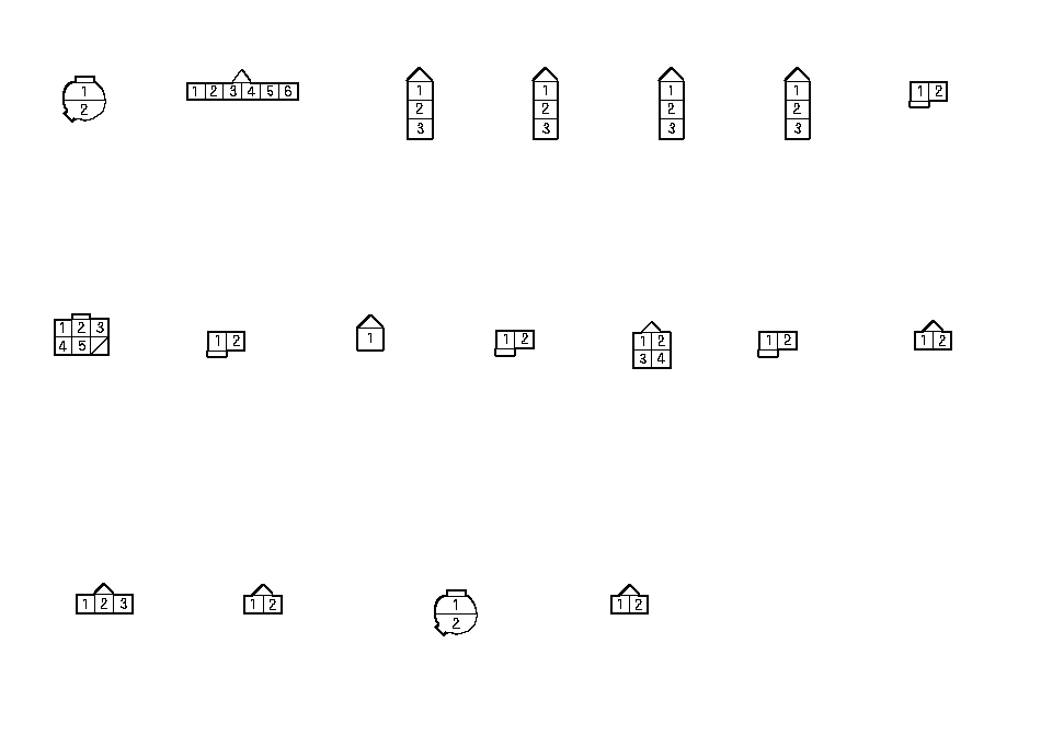 PSP SWITCH
(1)
(without EPS model)No. 1 IGINITION
COIL (3)No. 2 IGINITION
COIL (4)No. 3 IGINITION
COIL (5)No. 4 IGINITION
COIL (6)No. 4 INJECTOR
(7)6P
CONNECTOR
(8)No. 3 INJECTOR
(9)KNOCK SENSOR
(10)No. 2 INJECTOR
(11)ALTERNATOR
(12)No. 1 INJECTOR
(13)ENGINE MOUNT
CONTROL SOLENOID
VALVE (14) CKP SENSOR
(15)VTC OIL
CONTROL SOLENOID
VALVE (16)VTEC SOLENOID
VALVE (18)VTEC OIL PRESSURE
SWITCH (17)APP SENSOR
(2)
(K24A3 engine)NOTE:
· Connector with male terminals (double outline) : view from terminal side
· Connector with female terminals (single outline) : view from wire side
ECM/PCM Circuit Diagram (cont'd)
LHD model:
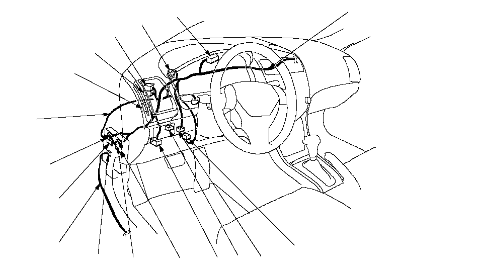 54321ENGINE
COMPARTMENT
WIRE
HARNESS1413FLOOR
WIRE
HARNESS1211109876DASHBOARD WIRE HARNESS
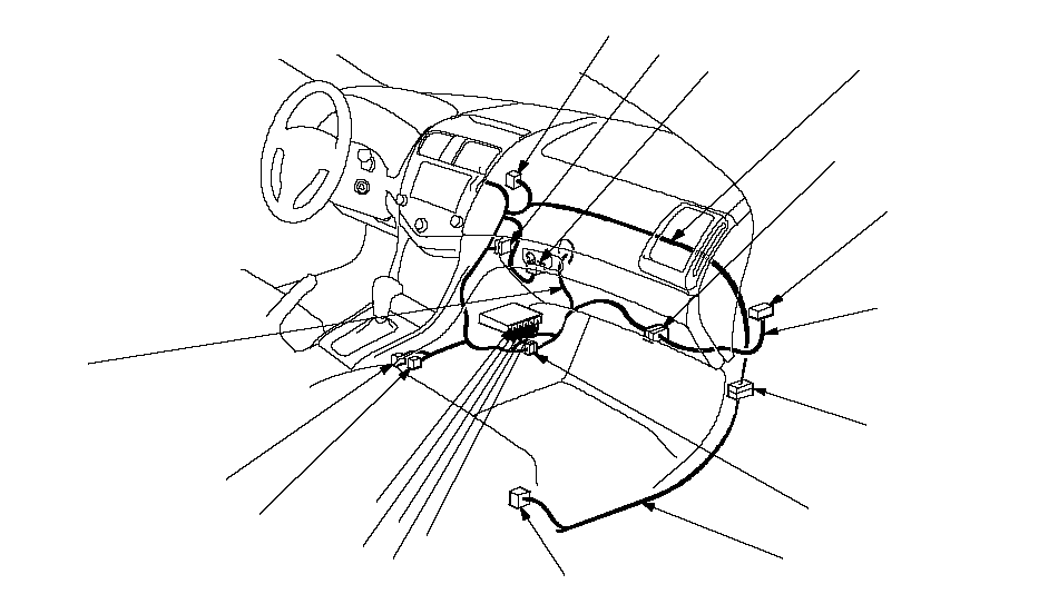 1517191820262729282122242325ENGINE
WIRE HARNESSFLOOR WIRE HARNESSDASHBOARD
WIRE HARNESSTHROTTLE ACTUATOR
CONTROL MODULE
SUBHARNESS16
 UNDER-DASH
FUSE/RELAY BOX (11)UNDER-DASH
FUSE/RELAY BOX (12)UNDER-DASH
FUSE/RELAY
BOX (13)UNDER-DASH
FUSE/RELAY
BOX (14)UNDER-DASH
FUSE/RELAY
BOX (10)28P JUNCTION
CONNECTOR (16)28P JUNCTION
CONNECTOR (15)GAUGE B (5)INERTIA
SWITCH (6)BRAKE PEDAL
POSITION
SWITCH (7)CLUTCH PEDAL
POSITION SWITCH
(8) DATA LINK CONNECTOR
(9)**ECM/PCM A (27)SHIFT LOCK
SOLENOID
(28) (A/T)SHIFT LEVER
(29) (A/T)ECM/PCM B (26)ECM/PCM D (24)ECM/PCM C (25)ECM/PCM E (23)13P CONNECTOR (21)SECONDARY HO2S
(SENSOR 2) (22)12P CONNECTOR (20)13P CONNECTOR (18)THROTTLE ACTUATOR
CONTROL MODULE (19)THROTTLE ACTUATOR
CONTROL MODULE
RELAY (17)28P JUNCTION
CONNECTOR (1)28P JUNCTION
CONNECTOR (2)28P JUNCTION
CONNECTOR (3)20P CONNECTOR
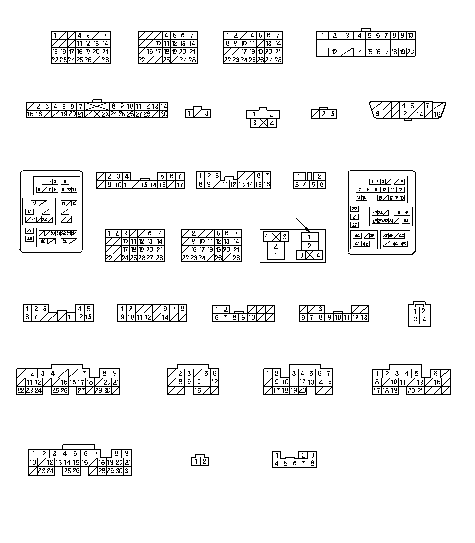
(4)NOTE:
· Connector with male terminals (double outline) : view from terminal side
· Connector with female terminals (single outline) : view from wire side
**: Connector with female terminals (single outline) : view from terminal side
ECM/PCM Circuit Diagram (cont'd)
RHD model:
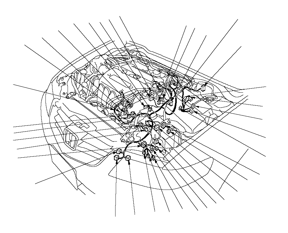 10234657891161719182011121413152627292830212224232531323533ENGINE
 WIRE HARNESSENGINE COMPARTMENT
WIRE HARNESS34
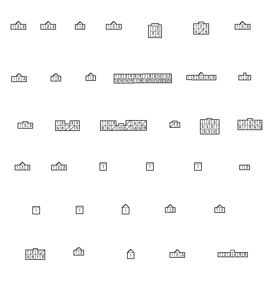 TRANSMISSION
RANGE SWITCH
(19) (A/T)MAP SENSOR
(1)TP SENSOR
(2)
(K20A6 engine)IAT
SENSOR
(3)COUNTERSHAFT
SPEED SENSOR
(4) (M/T)A/F SENSOR
(SENSOR 1)
(5)CMP SENSOR A
(7)CMP SENSOR B
(8)EVAP CANISTER
PURGE VALVE
(9)ECT
SENSOR
(10)EGR VALVE
(6)24P JUNCTION CONNECTOR(11)UNDER-HOOD
FUSE/RELAY
BOX (13)ELD(14)UNDER-HOOD
FUSE/RELAY
BOX (15)UNDER-HOOD
FUSE/RELAY
BOX (16)TEST
TACHOMETER
CONNECTOR
(17)10P CONNECTOR
(18) (A/T)SHIFT CONTROL
SOLENOID VALVE A
(26) (A/T)SHIFT CONTROL
SOLENOID VALVE C
(22) (A/T)SHIFT CONTROL
SOLENOID VALVE D
(27) (A/T)3RD CLUTCH
TRANSMISSION
FLUID
PRESSURE SWITCH
(28) (A/T)8P CONNECTOR
(31) (A/T)A/T CLUTCH
PRESSURE CONTROL
SOLENOID VALVE B
(29) (A/T)A/T CLUTCH
PRESSURE CONTROL
SOLENOID VALVE C
(30) (A/T)2ND CLUTCH
TRANSMISSION
FLUID
PRESSURE SWITCH
(33) (A/T)IAC VALVE
(34)
(K20A6 engine)MAINSHAFT
SPEED SENSOR
(20)COUNTERSHAFT
SPEED SENSOR
(21) (A/T)SHIFT CONTROL
SOLENOID VALVE E
(24) (A/T)ATF
TEMPERATURE
SENSOR
(25) (A/T) A/T CLUTCH
PRESSURE CONTROL
SOLENOID VALVE A
(32) (A/T)SHIFT CONTROL
SOLENOID VALVE B
(23) (A/T)THROTTLE BODY
(35)
(K24A3 engine)APP SENSOR
(12)
(K24A3 engine)NOTE:
· Connector with male terminals (double outline) : view from terminal side
· Connector with female terminals (single outline) : view from wire side
ECM/PCM Circuit Diagram (cont'd)
RHD model:
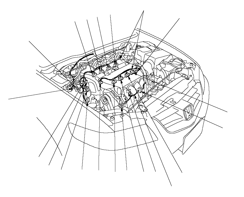 1023465789116171112141315ENGINE COMPARTMENT
WIRE HARNESSENGINE WIRE HARNESSG101STARTER SUBHARNESS
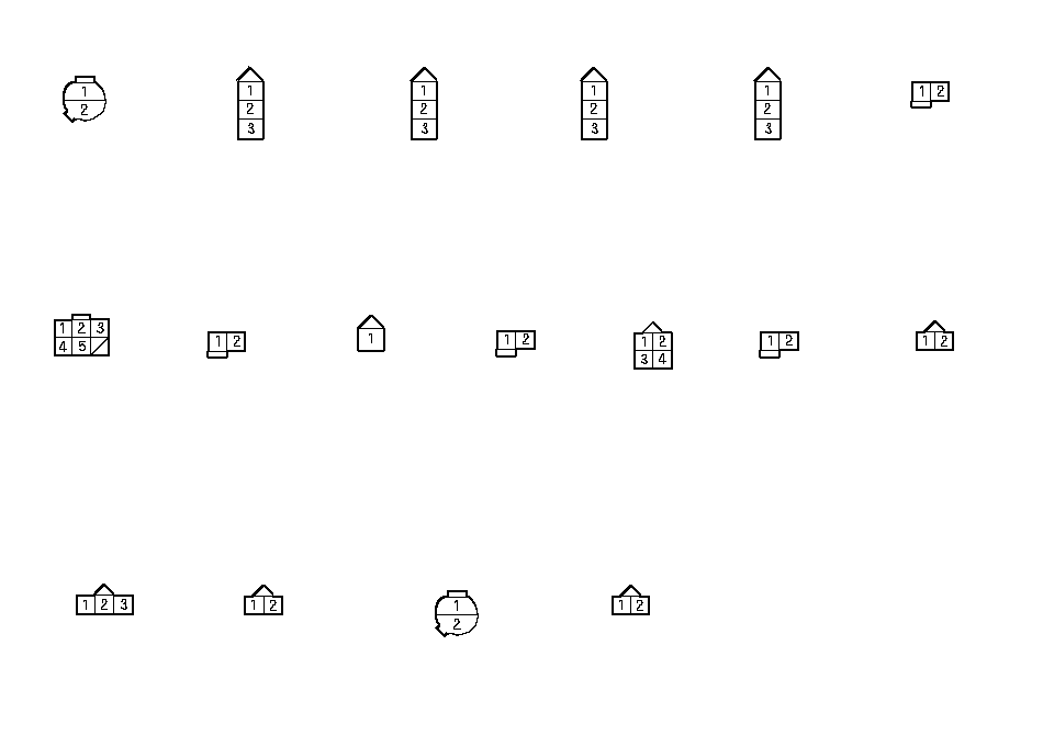 PSP SWITCH
(1)
(without EPS model)No. 1 IGINITION
COIL (2)No. 2 IGINITION
COIL (3)No. 3 IGINITION
COIL (4)No. 4 IGINITION
COIL (5)No. 4 INJECTOR
(6)6P
CONNECTOR
(7)No. 3 INJECTOR
(8)KNOCK SENSOR
(9)No. 2 INJECTOR
(10)ALTERNATOR
(11)No. 1 INJECTOR
(12)ENGINE MOUNT
CONTROL SOLENOID
VALVE (13) CKP SENSOR
(14)VTC OIL
CONTROL SOLENOID
VALVE (15)VTEC SOLENOID
VALVE (17)VTEC OIL PRESSURE
SWITCH (16)NOTE:
· Connector with male terminals (double outline) : view from terminal side
· Connector with female terminals (single outline) : view from wire side
ECM/PCM Circuit Diagram (cont'd)
RHD model:
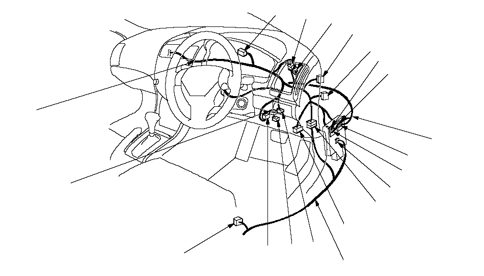 1023465789116171112141315DASHBOARD
 WIRE HARNESSENGINE
COMPARTMENT
WIRE HARNESS FLOOR WIRE HARNESS
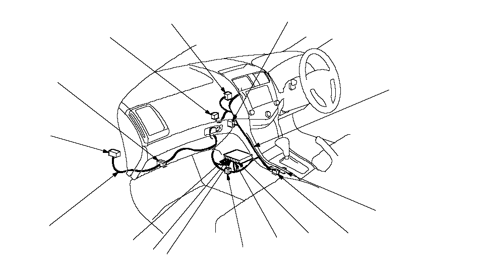 19182026272928302122242325THROTTLE ACTUATOR
CONTROL MODULE
SUBHARNESSDASHBOARD
WIRE HARNESS
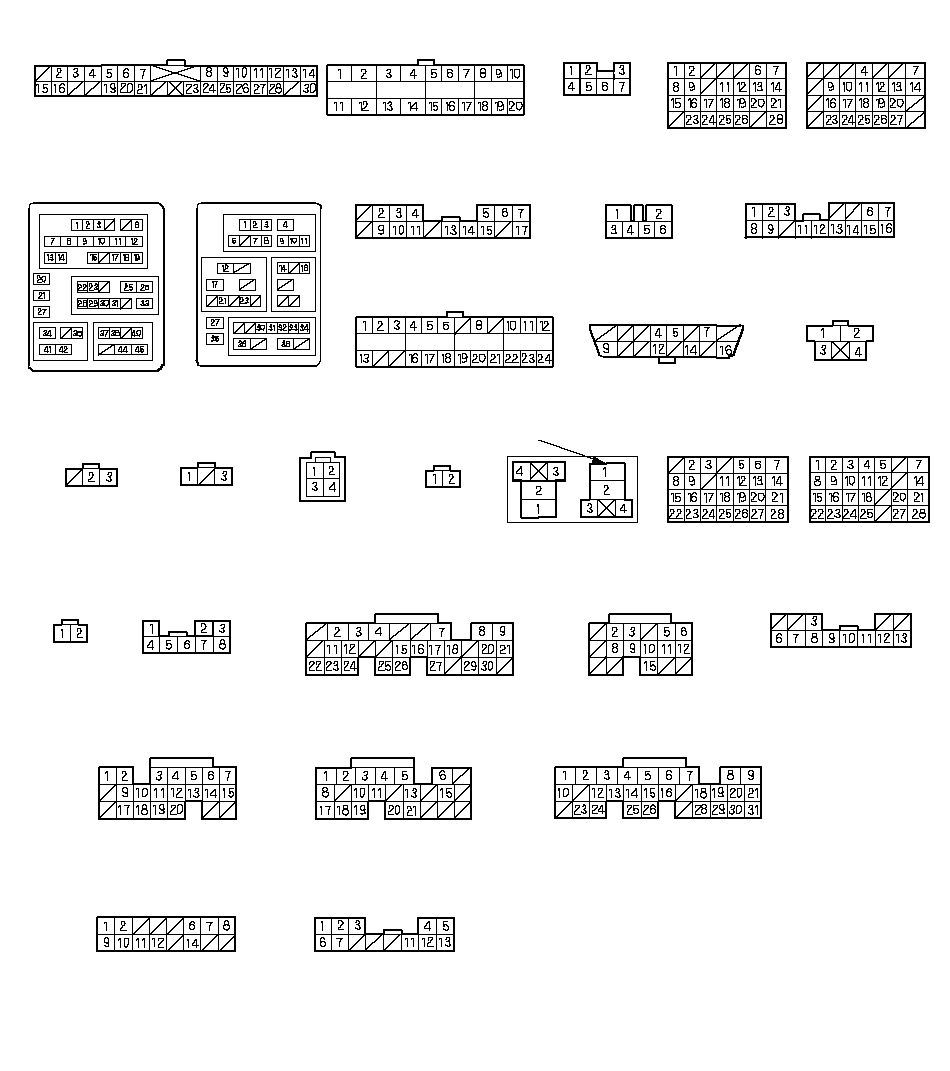 INERTIA
 SWITCH
(15)CLUTCH PEDAL
POSITION SWITCH
(14) ECM/PCM A (28)13P CONNECTOR (30)THROTTLE ACTUATOR
CONTROL MODULE (29)ECM/PCM B (27)ECM/PCM D (24)ECM/PCM C (26)ECM/PCM E (23)28P JUNCTION
CONNECTOR (20)28P JUNCTION
CONNECTOR (19)13P CONNECTOR (25)SECONDARY
HO2S (SENSOR 2)
(16)THROTTLE ACTUATOR
CONTROL MODULE
RELAY (18)SHIFT LOCK
SOLENOID
(21) (A/T)2P
CONNECTOR
(17) SHIFT LEVER
(22) (A/T)UNDER-DASH
FUSE/RELAY BOX (8)UNDER-DASH
FUSE/RELAY BOX (10)UNDER-DASH
FUSE/RELAY
BOX (9)UNDER-DASH
FUSE/RELAY
BOX (6)UNDER-DASH
FUSE/RELAY
BOX (7)BRAKE PEDAL
POSITION
SWITCH (13)DATA LINK CONNECTOR
(12)**24P CONNECTOR (11)28P JUNCTION
CONNECTOR (4)7P CONNECTOR
(3)20P CONNECTOR
(2)GAUGE B (1)28P JUNCTION
CONNECTOR (5)NOTE:
· Connector with male terminals (double outline) : view from terminal side
· Connector with female terminals (single outline) : view from wire side
**: Connector with female terminals (single outline) : view from terminal side
ECM/PCM Circuit Diagram (cont'd)
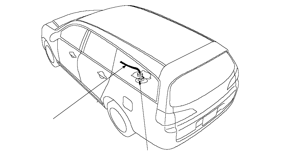 FLOOR
FLOORWIRE
HARNESS1
 FUEL PUMP (1)
- Connector with male terminals (double outline): view from terminal side
- Connector with female terminals (single outline): view from wire side