Blower-Heater Unit/Core Replacement
SRS components are located in this area.
Review the SRS component locations, and
precautions and procedures in the SRS section before performing repairs or service.
NOTE: LHD type is shown, RHD type is symmetrical.
| 1. | Disconnect the negative cable from the battery.
|
| 4. | Slide the hose clamps (A) back, then disconnect the inlet heater hose (B) and the outlet heater hose (C) from the heater core. Engine coolant will run out when the hoses are disconnected; drain it into a clean drip pan. Be sure not to let coolant spill on the electrical parts or the painted surfaces. If any coolant spills, rinse it off immediately.
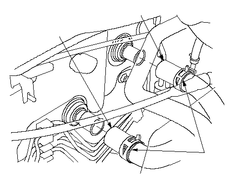 CBA CBA |
| 6. | Disconnect the drain hose (A) with air conditioning. Remove the clips (B), the mounting bolts, the mounting nuts, and the blower-heater unit (C).
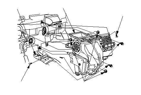 BBCA6 x 1.0 mm BBCA6 x 1.0 mm
9.8 N·m (1.0 kgf·m, 7.2 lbf·ft) |
| 7. | Remove the blower unit from the heater unit.
|
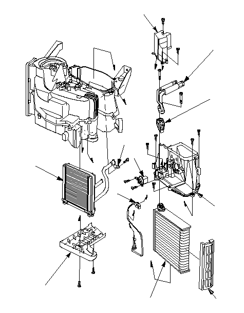
| 8. | Remove the self-tapping screws and the pipe cover (A). Remove the self-tapping screw and the pipe clamp (B), then carefully pull out the heater core (C) so you don't bend the inlet and outlet pipes.
 DEFIKJACHBG DEFIKJACHBG |
| 9. | With air conditioning; remove the self-tapping screws and the pipe cover (D). Remove the bolts, the inlet and outlet pipes (E), and the expansion valve (F). If necessary, remove the self-tapping screws and the blower resistor (G). Remove the evaporator temperature sensor connector (H), then remove the self-tapping screws and the duct (I). Pull out the evaporator core (J) with the plate (K).
|
| 10. | Install the heater core and the evaporator core (with air conditioning) in the reverse order of removal.
|
| 11. | Install the heater unit in the reverse order of removal, and note these items:
|