CVT System Description - Electronic Controls (CVT)
CVT System Description - Electronic Controls
General Operation
The continuously variable transmission (CVT) is an electrically controlled automatic transmission with drive and driven pulleys, and steel belt. The CVT provides non-stage speeds forward and 1 reverse. The entire unit is positioned in line with the engine.
Transmission
Around the out side of the flywheel is a ring gear which meshes with the starter pinion when the engine is being started. The transmission has four parallel shafts: the input shaft, the drive pulley shaft, the driven pulley shaft, and the final drive shaft. The input shaft is in line with the engine crankshaft. The drive pulley shaft and driven pulley shaft consist of movable and fixed face pulleys. Both pulleys are linked by the steel belt.The input shaft includes the sun gear and planetary gears with carrier. The drive pulley shaft includes the drive pulley and forward clutch. The driven pulley shaft includes the driven pulley, start clutch, and the secondary driven gear which is integral with the park gear. The final drive shaft is positioned between the secondary drive gear and the final driven gear. The final drive shaft includes the final drive gear and the secondary driven gear which serves to change the rotation direction, because the drive pulley shaft and driven pulley shaft rotate the same direction. When certain conditions of the planetary gears in the transmission are engaged by the forward clutch and the reverse brake, power is transmitted from the drive pulley shaft to the driven pulley shaft to provide [L], [S], [D], and [R] positions.
Electronic Control
The electronic control system consists of the powertrain control module (PCM), sensors, and solenoid valves. Shifting is electronically controlled for comfortable driving under all conditions. The PCM is located below the dashboard, behind the glove box.Hydraulic Control
The valve bodies include the main valve body, the ATF pump body, the control valve body, the ATF pass body, and the manual valve body. The ATF pump body is bolted on the main valve body. The main valve body is bolted on the flywheel housing. The control valve body is positioned outside of the transmission housing. The ATF pass body is positioned on the main valve body, and connected hydraulic circuit between the control valve body, main valve body and internal hydraulic circuit. The manual valve body is positioned on the intermediate housing.The ATF pump is the trochoid type, and the inner rotor is splined with the input shaft. The pulleys and clutches receive fluid from their respective feed pipes, and the reverse brake receives fluid from internal hydraulic circuit.
Shift Control
The PCM controls to shift pulley ratio the solenoids, which receiving input signal from the various sensors and switches located throughout the vehicle. The PCM actuates the CVT drive pulley pressure control valve and CVT driven pulley pressure control valve to change pulley control pressure. The drive pulley control pressure is applied to the drive pulley, and the driven pulley control pressure is applied to the driven pulley, and pulley ratio is changed to their effective ratio.Gear Selection
The shift lever has six positions: [P] PARK, [R] REVERSE, [N] NEUTRAL, [D] DRIVE, [S] SECOND, and [L] LOW.
| Position | Description |
|---|---|
| [P] PARK | Front wheels locked; park pawl engaged with park gear on the driven pulley shaft. The start clutch and forward clutch released. |
| [R] REVERSE | Reverse; reverse brake engaged. |
| [N] NEUTRAL | Neutral; the start clutch and forward clutch released. |
| [D] DRIVE | General driving; the transmission automatically adjusts to keep the engine at the best speed for driving under all conditions. |
| [S] SECOND | For rapid acceleration; the transmission selects a wider range of ratios to give better acceleration. |
| [L] LOW | For engine braking and power for climbing; the transmission shifts into the lowest range of the ratios. |
Starting is possible only in [P] and [N] positions because of a slide-type neutral-safety switch.
7Speed Mode
This CVT is provided with the 7Speed Mode in the [D] and [S] positions. The 7Speed Mode has two modes; the 7-speed automatic mode and 7-speed manual shifting mode. In the 7-speed automatic mode, the transmission can be shifted up and down automatically in 7-stage speeds of pulley ratios, and the steering shift switch is ready to be activated. When this switch is activated, the 7-speed automatic mode will be cancelled and 7-speed manual shifting mode comes into operation. In the 7-speed manual shifting mode, the driver can shift up and down manually in 7-stage speeds with using the steering shift switches; much like a manual transmission.Automatic Transaxle (A/T) Gear Position Indicator
The A/T gear position indicator in the instrument panel shows what position has been selected without looking down at the console. In the 7Speed Mode, the shift indicator next to the A/T gear position indicator will display speed-stage selected. The [M] indicator in the gauge assembly under the shift indicator comes ON while selecting the 7-speed manual shifting mode.Electronic Control System
Functional Diagram
The electronic control system consists of the powertrain control module (PCM), sensors, and solenoid valves. Shifting is electronically controlled for comfortable driving under all conditions.
The PCM inputs signals from the sensors, switches, and other control units, perform processing data, and outputs signals for engine control system and CVT control system. The CVT control system includes shift control/pulley pressure control, 7Speed Mode control, start clutch pressure control, reverse inhibitor control, and also a grade logic control is stored in the PCM. The PCM actuates the solenoid valves to control shifting transmission pulley ratios.
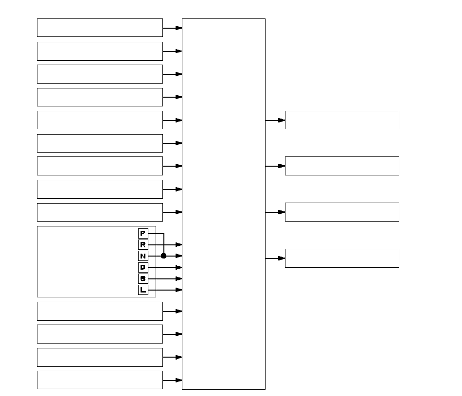 PCMCVT Control SystemThrottle Position Sensor SignalCrankshaft Position Sensor SignalManifold Absolute Pressure
Sensor SignalEngine Coolant Temperature
Sensor SignalIntake Air Temperature
Sensor SignalCVT Drive Pulley Speed Sensor
SignalCVT Speed Sensor SignalABS Control UnitTransmission Range
Switch SignalBrake Pedal Position Switch SignalData Link ConnectorShift Control/Pulley
Pressure ControlStart Clutch Pressure ControlA/T Gear Position
Indicator ControlCVT Driven Pulley Speed Sensor
SignalMain Switch (7Speed Mode) SignalSteering Shift Switch Signal7Speed Mode Control
Electronic Controls Location
NOTE: The illustration shows the RHD model; LHD symmetrical.
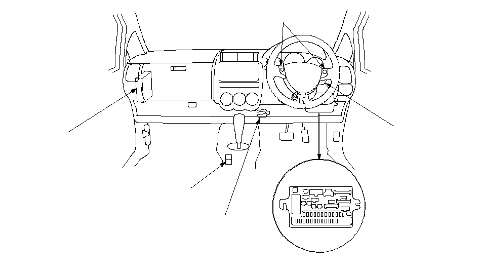 POWERTRAIN CONTROL
MODULE (PCM)SHIFT LOCK
SOLENOIDDATA LINK
CONNECTORUNDER-DASH
FUSE/RELAY BOXSTEERING SHIFT
SWITCHESMAIN SWITCH
(7SPEED MODE)
NOTE: The illustration shows the RHD model; LHD similar.
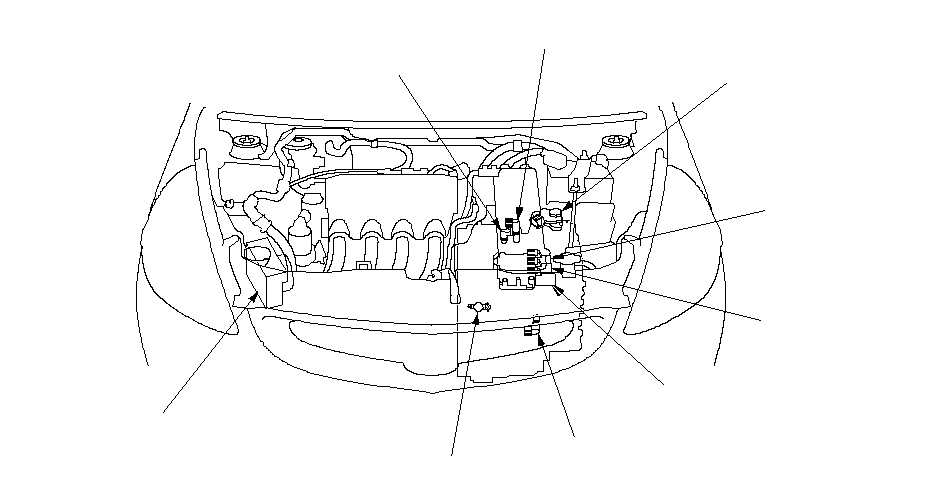 TRANSMISSION
RANGE SWITCHABS CONTROL
UNITINHIBITOR
SOLENOIDCVT DRIVE PULLEY
SPEED SENSORCVT START CLUTCH PRESSURE
CONTROL VALVECVT DRIVEN PULLEY
CONTROL VALVECVT DRIVEN PULLEY
SPEED SENSORCVT SPEED SENSORCVT DRIVE PULLEY
CONTROL VALVE
Electronic Control System (cont'd)
Shift Control/Pulley Pressure Control
The PCM compares actual driving conditions with memorized driving conditions to control shifting, and instantly determines a ratio of drive pulley and driven pulley by various signals sent from sensors and switches. The drive pulley drives the driven pulley by the steel belt at a ratio between 2.367-0.407 in non-stage in the [D] and [S] positions. In the [R] position, the ratio is set to 1.326 when pressing the accelerator, and to 2.367 when the accelerator released. When the pulley ratio is low (vehicle speed is low), the driven pulley receives high pulley pressure to hold large diameter, and the drive pulley receives low pressure to hold diameter of proportion to the driven pulley. When the pulley ratio is high (vehicle speed is high), the driven pulley receives low pressure, and drive pulley receives high. The PCM actuates the pulley pressure control valves to regulate optimum pulley pressure to the pulleys for reducing belt slippage and long belt life.
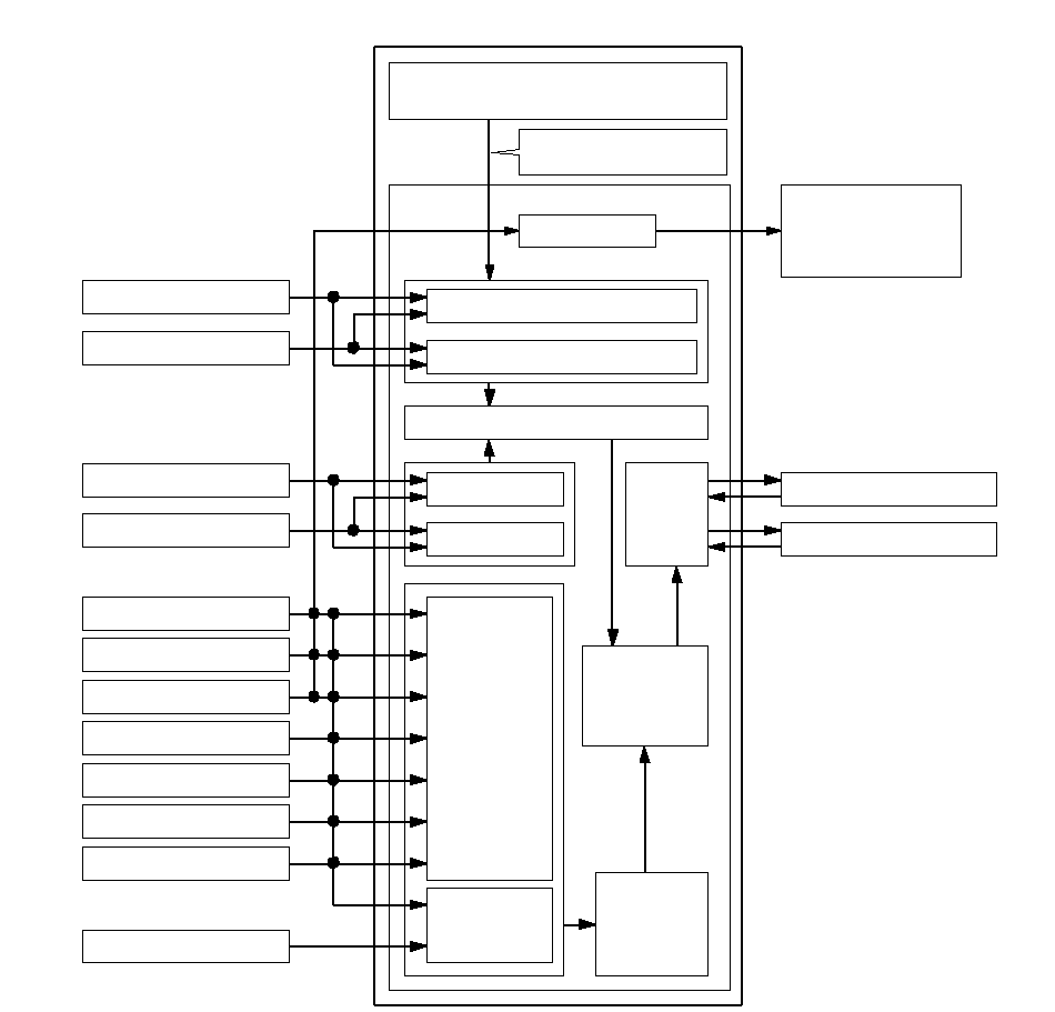 PCMPGM-FI Control SystemCorrection of engine
torque signal dataCVT Control SystemJudgment of
shift lever positionA/T Gear Position
Indicator
Position SignalCalculation of drive belt
transfer torqueFail-safe controlDecision of minimum required pulley pressureFail-safe controlCalculation of
pulley ratioCurrent
feedbackCalculation of
master target
of drive
pulley RPMDecision of
controlling
solenoid
currentFail-safe controlDecision of
driving pulley
pressureDriven Pulley Control SignalDrive Pulley Control SignalEngine RPM SignalManifold Absolute Pressure
Sensor SignalCVT Drive Pulley Speed
Sensor SignalCVT Driven Pulley Speed
Sensor SignalTransmission Range
Switch SignalThrottle Position Sensor
SignalCVT Drive Pulley Speed
Sensor SignalCVT Driven Pulley Speed
Sensor SignalCVT Speed Sensor SignalVehicle Speed SignalMain Switch
(7Speed Mode) SignalSteering Shift Switch
Signal
7Speed Mode Control
This CVT is provided with the 7Speed Mode in the [D] and [S] positions. The 7Speed Mode has two modes; the 7-speed automatic mode and 7-speed manual shifting mode. The transmission switches to the 7-speed automatic mode with push of the main switch (7SPEED MODE). In the 7-speed automatic mode, the transmission can be shifted up and down automatically in 7-stage speeds of pulley ratios, and the steering shift switch is ready to be activated. When this switch is activated, the 7-speed automatic mode will be cancelled and 7-speed manual shifting mode comes into operation. In the 7-speed manual shifting mode, the driver can shift up and down manually in 7-stage speeds with using the steering shift switches; much like a manual transmission.
The 7Speed Mode is cancelled by pressing the main switch (7SPEED MODE) or when moving the shift lever to other position.
The main switch (7SPEED MODE) (A) and the steering shift switches (B) are installed on the steering wheel. The driver can select the modes and speed stages with pressing the switches without taking either hand off the steering wheel.
 AB
ABThe shift indicator (A) and [M] indicator (B) are in the gauge assembly (C) next to the A/T gear position indicator (D).
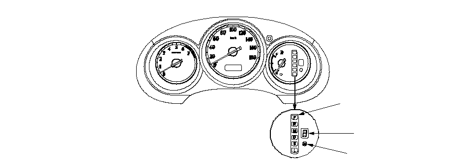 CDAB
CDABIn the 7-speed manual shifting mode, the [M] indicator comes on, and the shift indicator displays the number of the selected speed stage.
Electronic Control System (cont'd)
7Speed Mode Control (cont'd)
7-speed Automatic Mode
When the transmission is switched to the 7-speed automatic mode by pressing the main switch (7SPEED MODE) while driving in the [D] or [S] position, the transmission sets the optimum speed stage automatically according to conditions such as the balance between the throttle opening and vehicle speed. The transmission shifts to the over-drive range under certain conditions coasting in 7th speed.
When switched to the 7-speed automatic mode at a vehicle stop in the [D] or [S] position, the transmission shifts into 1st speed stage, and the vehicle starts off in 1st speed. The shift indicator displays the number of the speed stage.
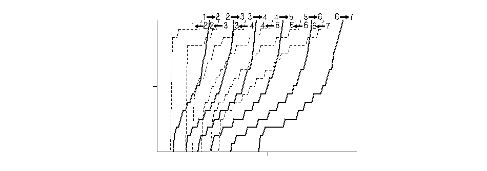 062 mph (100 km/h)Vehicle speed50%Throttle opening7-speed automatic mode
shift schedule
7-speed Manual Shifting Mode
The transmission is switched to the 7-speed manual shifting mode by pushing the steering shift switches from the 7-speed automatic mode, and the [M] indicator comes ON. With pushing the plus (+) switch, the transmission upshifts to the next higher speed stage, and with pusing the minus (-) switch, the transmission downshifts. The shift indicator displays the number of the selected speed stage.
When the vehicle is coasting in such a speed that the engine will over-rev by downshifting the transmission, the transmission cannot downshift until the vehicle reaches the downshift allowable speed. This mode also has automatic upshifting area to prevent engine over-revving, and downshifting area so the vehicle can run smooth and more power to cope with upcoming acceleration. The transmission shifts to the over-drive range under certain conditions coasting in 7th speed.
When the vehicle decelerates to a stop, the transmission shifts to 2nd speed stage automatically, not to 1st speed.The transmission can be shifted to 2nd speed stage by pushing the plus (+) switch while the vehicle is stopped, and the vehicle can start off in 2nd speed.
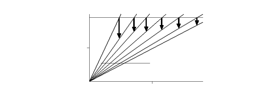 62 mph (100 km/h)Vehicle speed3,000Engine RPM
rpm (min-1)AUTOMATIC DOWNSHIFTING AREAAUTOMATIC UPSHIFTING AREA1st2nd3rd4th5th6th7th
Start Clutch Pressure Control
Hydraulic-controlled start clutch works smooth starting-off and creeping in [D], [S], [L], and [R] positions like the torque converter. The PCM inputs signals from the sensors and switches, and actuates the start clutch pressure control valve to regulate the start clutch pressure.
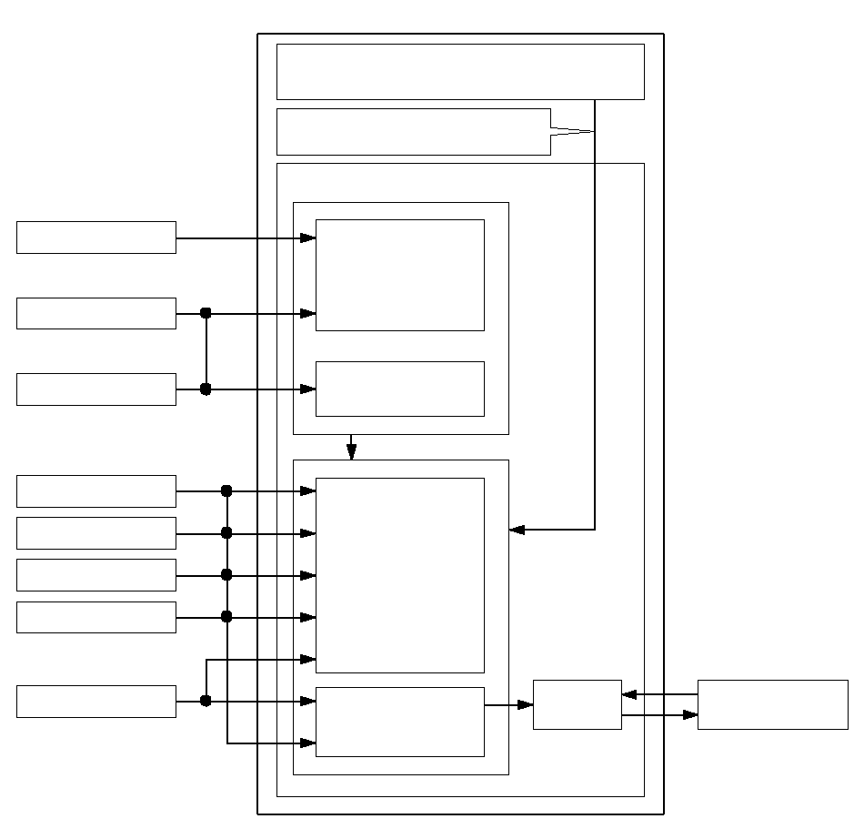 PCMPGM-FI Control SystemCorrection of intake air temperature
sensor signal data and othersCVT Control SystemJudgment of
driving modeFail-safe controlDecision of start
clutch control
pressureFail-safe controlEngine RPM SignalManifold Absolute
Pressure Sensor SignalCVT Drive Pulley Speed
Sensor SignalCVT Driven Pulley Speed
Sensor SignalTransmission Range
Switch SignalThrottle Position
Sensor SignalCVT Speed Sensor
SignalCurrent
feedbackStart Clutch Pressure
Control SignalBrake Pedal Position
Switch Signal
Electronic Control System (cont'd)
PCM Terminal Connections
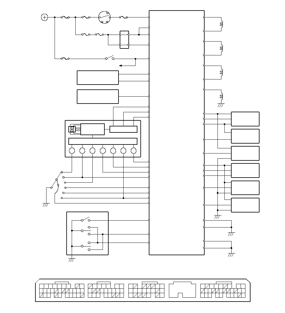 272821208411320191112151311125A (31P)B (24P)C (22P)E (31P)PCM Connector Terminal Locations312622973151829242320111210815167211718161413765432823242728293021201918151211101234567926249162225PG2A24LG1A4A5PG1LG2A23LED CE20E21LED BE8LED AInput CircuitS-DNS-UPS-UPS-DNM INDB11S INDB12MPGM-FIDR LS-DR LS+E11D INDSCSE29IG1BATTERYDN LS+SC LS+B7B16B24IG1E9PCMC6SOL INHE23K-LINEBRAKE LIGHTSE22BK SWIGP2A2TPSA15ATP LC11C9ATP DATP RC10RLDPNSWITCHRANGETRANSMISSIONLNRPC20C12ATP NPC1DN LS-C8SC LS-GAUGE ASSEMBLYIGNITION SWITCHA20VCC2A10SG2SENSORTEMPERATUREENGINE COOLANTCPUSATP SVABSA18POSITION SWITCHBRAKE PEDALB8ECTTHROTTLEPOSITION SENSORSOLENOIDINHIBITORBATABS CONTROL UNITDDimming CircuitMAINRELAY 1E7MRLYIGP1A3DATA LINK CONNECTORSC13M-SWS-UPB20B19S-DNVALVEPRESSURE CONTROLCVT START CLUTCHC7NDRCVT DRIVEPULLEY SPEEDSENSORSG1A11VCC1A21A19MAP (PB)PRESSURE (MAP)ABSOLUTEMAINFOLDSENSORSENSORPULLEY SPEEDCVT DRIVENNDNC15SENSORCVT SPEEDC22VEL1C16IG1 HOT in ON (II)and START (III)CONTROL VALVESTEERING SHIFT SWITCHMAIN SWITCH(7SPEED MODE)/7SPEED MODECVT DRIVENCONTROL VALVECVT DRIVEPULLEY PRESSUREPULLEY PRESSURE
PCM Inputs and Outputs
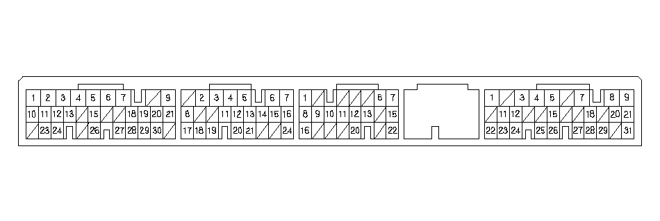 PGM Connector Terminal LocationsA (31P)B (24P)C (22P)E (31P)
| Terminal Number | Wire Color | Signal | Description | Measuring Conditions/Terminal Voltage |
|---|---|---|---|---|
| A2 | YEL/BLK | IGP2 | Power supply circuit from main relay | With ignition switch ON (II): Battery voltage With ignition switch OFF: 0 V |
| A3 | YEL/BLK | IGP1 | Power supply circuit from main relay | With ignition switch ON (II): Battery voltage With ignition switch OFF: 0 V |
| A4 | BLK | PG2 | Ground | |
| A5 | BLK | PG1 | Ground | |
| A10 | GRN/BLK | SG2 | Sensor ground | |
| A11 | GRN/WHT | SG1 | Sensor ground | |
| A18 | BLU/WHT | VABS | Vehicle speed sensor signal input | With ignition switch ON (II): About 5 V With ignition switch OFF: 0 V |
| A20 | YEL/BLU | VCC2 | Power supply circuit for sensors | With ignition switch ON (II): About 5 V With ignition switch OFF: 0 V |
| A21 | YEL/RED | VCC1 | Power supply circuit for sensors | With ignition switch ON (II): About 5 V With ignition switch OFF: 0 V |
| A23 | BRN/BLK | LG2 | Ground | |
| A24 | BRN/BLK | LG1 | Ground |
| Terminal Number | Wire Color | Signal | Description | Measuring Conditions/Terminal Voltage |
|---|---|---|---|---|
| B7 | GRN/WHT | DN LS + | CVT driven pulley pressure control valve power supply positive electrode | With ignition switch ON (II): Pulsing signal |
| B11 | RED/WHT | M IND | [M] indicator control | When 7-speed manual shifting mode is selected: About 6 V In other than manual shifting mode: 0 V |
| B12 | LT GRN | S IND | [S] indicator control | In the [S] position: About 6 V In other than the [S] position: 0 V |
| B16 | YEL | SC LS + | CVT start clutch pressure control valve power supply positive electrode | With ignition switch ON (II): Pulsing signal |
Electronic Control System (cont'd)
PCM Inputs and Outputs (cont'd)
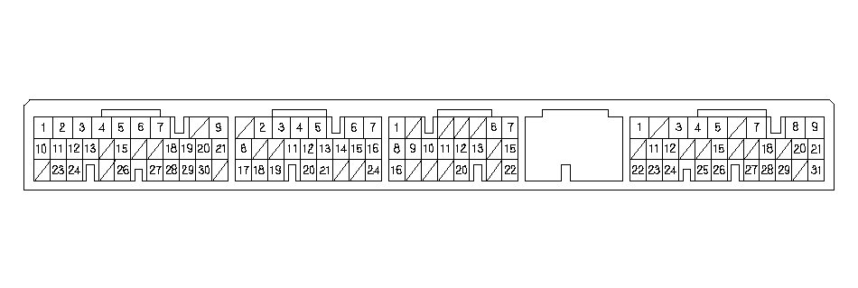 PCM Connector Terminal LocationsA (31P)B (24P)C (22P)E (31P)
| Terminal Number | Wire Color | Signal | Description | Measuring Conditions/Terminal Voltage |
|---|---|---|---|---|
| B19 | LT GRN/RED | S-DN | Downshift switch signal input | With ignition switch ON (II): Downshift switch pressed: 0 V Downshift switch released: About 5 V |
| B20 | YEL | S-UP | Upshift switch signal input | With ignition switch ON (II): Upshift switch pressed: 0 V Upshift switch released: About 5 V |
| B24 | BLU/WHT | DR LS+ | CVT drive pulley pressure control valve power supply positive electrode | With ignition switch ON (II): Pulsing signal |
| Terminal Number | Wire Color | Signal | Description | Measuring Conditions/Terminal Voltage |
|---|---|---|---|---|
| C1 | PNK/BLK | DN LS - | CVT driven pulley pressure control valve power supply negative electrode | With ignition switch ON (II): Pulsing signal |
| C6 | GRN/BLK | SOL INH | Inhibitor solenoid control | With inhibitor solenoid ON (II): Battery voltage With inhibitor solenoid OFF: 0 V |
| C7 | RED/BLU | NDR | CVT drive pulley speed sensor signal input | With ignition switch ON (II): 0 V or about 5 V With engine at idle in the [N] position: About 2.5 V |
| C8 | PNK/BLU | SC LS - | CVT start clutch pressure control valve power supply negative electrode | With ignition switch ON (II): Pulsing signal |
| C9 | BLU/WHT | ATP S | Transmission range switch [S] position input | In the [S] position: 0 V In other than the [S] position: About 5 V |
| C10 | WHT | ATP R | Transmission range switch [R] position input | In the [R] position: 0 V In other than the [R] position: About 10 V |
| C11 | BLU | ATP L | Transmission range switch [L] position input | In the [L] position: 0 V In other than the [L] position: About 10 V |
| C12 | LT GRN | ATP NP | Transmission range switch [P] and [N] positions input | In the [P] and [N] positions: 0 V In other than the [P] and [N] positions: About 5 V |
| Terminal Number | Wire Color | Signal | Description | Measuring Conditions/Terminal Voltage |
|---|---|---|---|---|
| C13 | YEL | M-SW | Main switch (7Speed Mode) signal input | In the 7Speed Mode: 0 V Released the 7Speed Mode: About 5 V |
| C15 | WHT | NDN | CVT driven pulley speed sensor signal input | With ignition switch ON (II): 0 V or about 5 V With engine at idle in the [N] position: About 2.5 V |
| C16 | GRN/YEL | DR LS - | CVT drive pulley control valve power supply negative electrode | With ignition switch ON (II): Pulsing signal |
| C20 | PNK | ATP D | Transmission range switch [D] position input | In the [D] position: 0 V In other than the [D] position: About 5 V |
| C22 | WHT/RED | VEL1 | CVT speed sensor signal input | With ignition switch ON (II): 0 V or about 5 V With driving (front wheels rotating): About 2.5 V |
| Terminal Number | Wire Color | Signal | Description | Measuring Conditions/Terminal Voltage |
|---|---|---|---|---|
| E8 | BLU/WHT | LED A | Shift indicator control | With ignition switch ON (II) and not in the 7Speed Mode: About 5 V In the 7Speed Mode
|
| E11 | PNK | D IND | [D] indicator control | When ignition switch is first turned ON (II): About 6 V for 2 seconds In the [D] position: About 6 V |
| E20 | GRN/BLK | LED C | Shift indicator control | With ignition switch ON (II) and not in the 7Speed Mode: About 5 V In the 7Speed Mode
|
| E21 | RED/WHT | LED B | Shift indicator control | With ignition switch ON (II) and not in the 7Speed Mode: About 5 V In the 7Speed Mode
|
| E22 | WHT/BLK | BK SW | Brake pedal position switch signal input | Brake pedal pressed: Battery voltage Brake pedal released: 0 V |
| E29 | BRN | SCS | SCS terminal signal input | With ignition switch ON (II)
|
Circuit Diagram
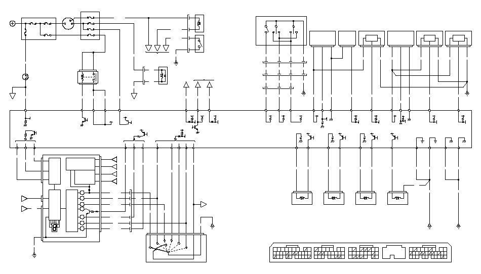 CVT DRIVE PULLEYCONTROL VALVEPRESSUREINHIBITOR SOLENOID252216924269765432110111215181920213029282724238234567131416181721761158101211202324291815379222631PCM Connector Terminal LocationsE (31P)C (22P)B (24P)A (31P)512111315121119201314820212827G402S-DNS-UPGRN/WHTWHT/BLUBRN/WHTBLK2BLK143BRN/WHTWHT/BLUGRN/WHTS-UPS-DNBLK2345GRN/WHTWHT/BLUBRN/WHTLT GRN/REDYELYELTo 5VVALVECVT START CLUTCHPRESSURE CONTROLPRESSURECVT SPEED SENSORSPEED SENSORCVT DRIVEN PULLEYPRESSURE SENSORMANIFOLD ABSOLUTECVT DRIVE PULLEYSPEED SENSORSENSORENGINE COOLANT TEMPERATURESENSORTHROTTLE POSITIONG101VEL1C22WHT/REDBRN/BLKYEL/RED213WHTC15NDN312YEL/REDBRN/BLKRED/GRNYEL/RED(PB)VCC1A21MAPA19SG1A11312YEL/REDGRN/WHTBRN/BLKYEL/BLU2BLK12GRN/YELBLU/WHTB24C1621DR LS+DR LS-SC LS-SC LS+DN LS+S-UPB20PG2A4BLKA5PG1G101BLKBLKBRN/BLKCONTROL VALVECVT DRIVEN PULLEY12NDRC7RED/BLU13ECTB8RED/WHT12BRN/BLKG101DN LS-SOL INHLG1C1B7C8B16C6A24POWERTRAIN CONTROL MODULE (PCM)21PNK/BLKGRN/WHTYELPNK/BLUGRN/BLKBRN/BLKA23LG2GRN/BLKA10SG2123RED/BLKYEL/BLUA15TPSA20VCC2B19S-DNC13M-SWMODE7SPEEDMAIN SWITCH(7SPEED MODE)/STEERING SHIFT SWITCHBLU/WHTRED/WHTGRN/BLKVABSA18BLU/WHTSCSE29BRNRED/WHTE23K-LINEABSCONTROLUNITDATA LINKCONNECTORE8LED ALED BE21LED CE20B4CIRCUITINPUTINDICATORSHIFTB2B2B7B7B1B1B6B6RED/WHTB11M INDLT GRNB12S INDBOXC5BRN/WHTB11MC5B2B7B1B6KEY INTERLOCKCIRCUITSHIFT LOCK CIRCUITNo.16 (7.5A)DIMMINGCIRCUITRELAYBLU/BLKWHTRED/BLKASSEMBLYYEL/BLKGAUGECONNECTORCONNECTORUNDER-DASHFUSE/RELAY BOXSWITCHBRAKEB5B3A2UNDER-DASHFUSE/RELAYYELPNKD INDE11NPLATPATPSBLUBLU/WHTRED/BLKWHTBLU/BLKB10B8B9B12B13B14LNRPDGAUGE ASSEMBLYG401BLKBLU/REDYEL/BLUYELYEL/BLKBLURED213434GAUGEYEL/REDNo.20 (15A)LOCKSOLENOIDSHIFTKEYKEYINTERLOCKSWITCHSOLENOIDNo.16 (7.5A)No.11 (15A)No.17 (7.5A)IG1ACC9BLUC11LSCONNECTORASSEMBLYCUTSTARTERBK SWE22WHT/GRNWHT/BLKPOSITIONPEDALNo.16(10A)LT BLUC12BATATPATPC10C20C9ATPDWHTPNKBLU/WHTG101BLKSRG501BLKC5A9IGNITION SWITCHGAUGE ASSEMBLYCPU67283410PRNTRANSMISSION RANGE SWITCHDSTENo.6 (40A)BATTERYUNDER-HOOD FUSE/RELAY BOXTo 12VPOWERTRAIN CONTROL MODULE (PCM)No.1 (80A)RELAY 1MAINPGM-FIRED/YELYEL/BLKMRLYE7A3IGP1A2IGP2E9BLK/YELIG1No.3 (50A)To 5V