DTC Troubleshooting: P1886 (35-1) (CVT)
DTC Troubleshooting: P1886 (35-1)
| DTC P1886: | Problem in CVT Driven Pulley Speed Sensor Circuit |
NOTE: Record all freeze data before you troubleshoot.
| 1. | Check whether the DTC for manifold absolute pressure (MAP) sensor is indicated. Is the DTC for MAP sensor indicated? YES - Perform the MAP sensor troubleshooting, and recheck for DTC P1886 after troubleshooting. NO - Go to 2. |
| 2. | Turn the ignition switch OFF. |
| 3. | Check for continuity between PCM connector terminal A23 and body ground, and between terminal A24 and body ground.
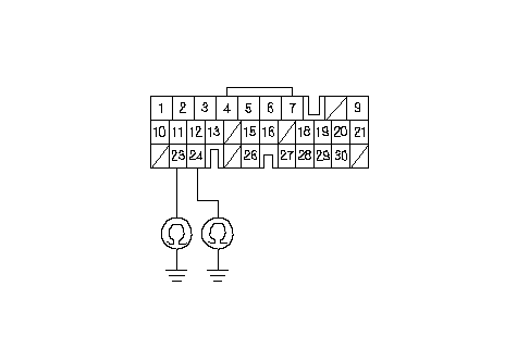 Wire side of female terminalsPCM CONNECTOR A (31P)LG2 (BRN/BLK)LG1 (BRN/BLK) Wire side of female terminalsPCM CONNECTOR A (31P)LG2 (BRN/BLK)LG1 (BRN/BLK)Are there continuity? YES - Go to 4. NO - Repair open in the wire PCM connector terminals A23 and A24, and ground (G101), or repair poor ground (G101).n |
| 4. | Disconnect CVT driven pulley speed sensor connector. |
| 5. | Turn the ignition switch ON (II). |
| 6. | Measure the voltage between CVT driven pulley speed sensor connector terminal No. 1 and body ground.
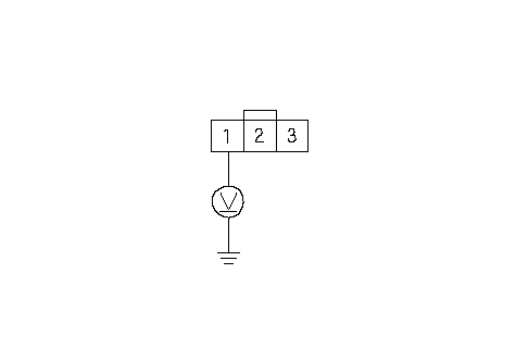 Wire side of female terminalsCVT DRIVEN PULLEY SPEED Wire side of female terminalsCVT DRIVEN PULLEY SPEEDSENSOR CONNECTORVCC1 (YEL/RED) Is there about 5 V? YES - Go to 7. NO - Go to 20. |
| 7. | Turn the ignition switch OFF. |
| 8. | Disconnect the battery negative terminal. |
| 9. | Disconnect PCM connector C (22P). |
| 10. | Check for continuity between CVT driven pulley speed sensor connector terminal No. 2 and body ground.
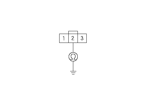 Wire side of female terminalsCVT DRIVEN PULLEY SPEED Wire side of female terminalsCVT DRIVEN PULLEY SPEEDSENSOR CONNECTORNDN (WHT) Is there continuity? YES - Repair short to ground in the wire between PCM connector C15 and the CVT driven pulley speed sensor connector.n NO - Go to 11. |
| 11. | Check for continuity between CVT driven pulley speed sensor connector terminal No. 3 and body ground.
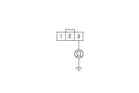 Wire side of female terminalsCVT DRIVEN PULLEY SPEED Wire side of female terminalsCVT DRIVEN PULLEY SPEEDSENSOR CONNECTORLG1 (BRN/BLK) Is there continuity? YES - Go to 12. NO - Repair open in the wire between the CVT driven pulley speed sensor connector terminal No. 3 and ground (G101), or repair poor ground (G101).n |
| 12. | Reconnect PCM connector C (22P), then reconnect the battery negative terminal. |
| 13. | Turn the ignition switch ON (II). |
| 14. | Measure the voltage between CVT driven pulley speed sensor connector terminals No. 2 and No. 3.
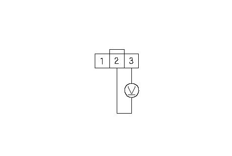 Wire side of female terminalsCVT DRIVEN PULLEY SPEED Wire side of female terminalsCVT DRIVEN PULLEY SPEEDSENSOR CONNECTORLG1 (BRN/BLK)NDN (WHT) Is there about 5 V? YES - Go to 15. NO - Go to 25. |
| 15. | Connect CVT driven pulley speed sensor connector. |
| 16. | Measure the voltage between PCM connector terminals C15 and A23 or A24.
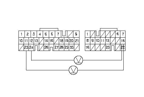 Wire side of female terminalsPCM CONNECTORSC (22P)A (31P)LG2 (BRN/BLK)LG1 (BRN/BLK)NDN (WHT) Wire side of female terminalsPCM CONNECTORSC (22P)A (31P)LG2 (BRN/BLK)LG1 (BRN/BLK)NDN (WHT)Is there about 0 V or 5 V? YES - Go to 17. NO - Replace the CVT driven pulley speed sensor.n |
| 17. | Shift to [P] position. |
| 18. | Start the engine, and let it idle. |
| 19. | With engine idling, measure the voltage between PCM connector terminals C15 and A23 or A24.
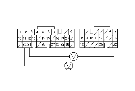 Wire side of female terminalsPCM CONNECTORSC (22P)A (31P)LG2 (BRN/BLK)LG1 (BRN/BLK)NDN (WHT) Wire side of female terminalsPCM CONNECTORSC (22P)A (31P)LG2 (BRN/BLK)LG1 (BRN/BLK)NDN (WHT)Is there 1.5-3.5 V? YES - Check for loose terminal fit in the PCM connectors. If necessary, substitute a known-good PCM and recheck.n NO - Replace the CVT driven pulley speed sensor.n |
| 20. | Measure the voltage between PCM connector terminals A21 and A23 or A24.
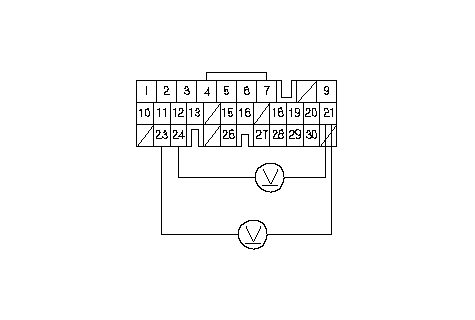 Wire side of female terminalsPCM CONNECTOR A (31P)LG2 (BRN/BLK)LG1 (BRN/BLK)VCC1 Wire side of female terminalsPCM CONNECTOR A (31P)LG2 (BRN/BLK)LG1 (BRN/BLK)VCC1(YEL/RED) Is there 4.75-5.25 V? YES - Repair open in the wire between PCM connector terminal A21 and the CVT driven pulley speed sensor connector.n NO - Go to 21. |
| 21. | Turn the ignition switch OFF. |
| 22. | Disconnect the battery negative terminal. |
| 23. | Disconnect PCM connector A (31P). |
| 24. | Check for continuity between PCM connector terminal A21 and body ground.
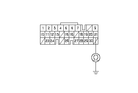 Wire side of female terminalsPCM CONNECTOR A (31P)VCC1 (YEL/RED) Wire side of female terminalsPCM CONNECTOR A (31P)VCC1 (YEL/RED)Is there continuity? YES - Repair short to ground in the wire between PCM connector terminal A21 and the CVT driven pulley speed sensor connector.n NO - Check for loose terminal fit in the PCM connectors. If necessary, substitute a known-good PCM and recheck.n |
| 25. | Measure the voltage between PCM connector terminals C15 and A23 or A24.
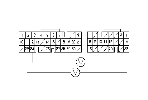 Wire side of female terminalsPCM CONNECTORSC (22P)A (31P)LG2 (BRN/BLK)LG1 (BRN/BLK)NDN (WHT) Wire side of female terminalsPCM CONNECTORSC (22P)A (31P)LG2 (BRN/BLK)LG1 (BRN/BLK)NDN (WHT)Is there about 5 V? YES - Repair open in the wire between PCM connector terminal C15 and the CVT driven pulley speed sensor connector.n NO - Check for loose terminal fit in the PCM connectors. If necessary, substitute a known-good PCM and recheck.n |