How to Troubleshoot the SRS
How to Troubleshoot the SRS
DTC (Diagnostic Trouble Codes)
The self-diagnostic function of the SRS system allows it to locate the causes of system problems and then store this information in memory. For easier troubleshooting, this data can be retrieved via a data link circuit.
- When you turn the ignition switch ON (II), the SRS indicator will come on. If it goes off after 6 seconds, the system is normal.
- If there is an abnormality, the system locates and defines the problem, stores this information in memory, and turns the SRS indicator on. The data will remain in the memory even when the ignition switch is turned off or if the battery is disconnected.
- When you connect the Honda PGM Tester to the 16P data link connector (DLC) to short the SCS terminal, and turn the ignition switch ON (II), the SRS indicator will indicate the diagnostic trouble code (DTC) by the number of blinks.
- After reading and recording the DTC, proceed with the troubleshooting procedure for this code.
Precautions
- Use only a digital multimeter to check the system. If it¢s not a Honda multimeter, make sure it's output is 10 mA ( 0.01A) or less when switched to the smallest value in the ohmmeter range. A tester with a higher output could damage the airbag circuit or cause accidental airbag deployment and possible injury.
- Whenever the ignition switch is ON (II), or has been turned OFF for less than 3 minutes, be careful not to bump the SRS unit; the airbags could accidentally deploy and cause damage or injuries.
- Before you remove the SRS main harness, disconnect the driver's airbag connector, the front passenger's airbag connector, both side airbag connectors, and both seat belt tensioner connectors.
- Make sure the battery is sufficiently charged. If the battery is dead or low, measuring values won't be correct.
- Do not touch a tester probe to the terminals in the SRS unit or harness connectors, and do not connect the terminals with a jumper wire. Use only the backprobe set and the Honda PGM Tester. Backprobe spring-loaded lock type connectors correctly.
Reading the DTC
When the SRS indicator is on, read the DTC using either of the following methods:
PGM Tester ‘‘SRS'' Menu Method:
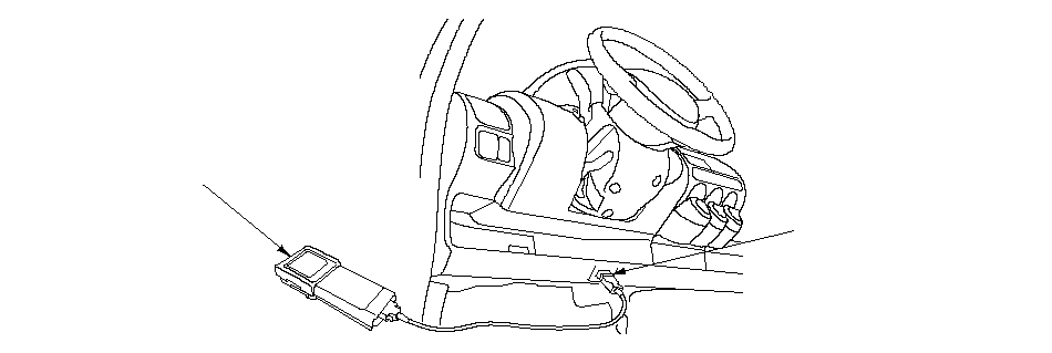
Connect the Honda PGM Tester (A) to the 16P Data Link Connector (DLC) (B), and follow the Tester's prompts in the
‘‘SRS'' menu. If the Tester indicates no DTC, DTC 9-1, or DTC 9-2, double-check by selecting ‘‘SCS'' on the display, and watching the SRS indicator.
 AB
AB‘‘SCS'' Menu Method (retrieving the flash codes)
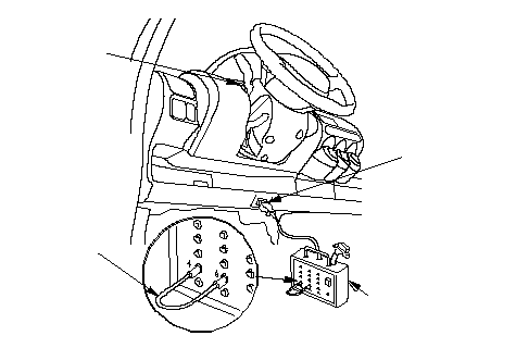
The SRS indicator (A) indicates the DTC by the number of blinks when the DLC pin box (B) is connected to the Data Link Connector (DLC) 16P (C).
| 1. | Make sure the ignition switch is OFF, and wait for 10 seconds. Then connect the DLC pin box (A) to the Data Link Connector (DLC) 16P. If you don't wait 10 seconds, the SRS unit won't be completely reset or output DTCs.
 DACB DACB07WAJ-0010100 |
| 2. | Connect the DLC pin box terminals No.4 and No.9 with a jumper wire (D), and push the operation switch. |
| 3. | Turn the ignition switch ON (II). The SRS indicator comes on for about 6 seconds, and then goes off. Then it will indicate the DTC. |
| 4. | Read the DTC. |
| 5. | Turn the ignition switch OFF, and wait for 10 seconds. Then disconnect the DLC pin box from the Data Link Connector (DLC) 16P. |
| 6. | Proceed with the troubleshooting procedure for this DTC. |
Patterns of DTC Indications:
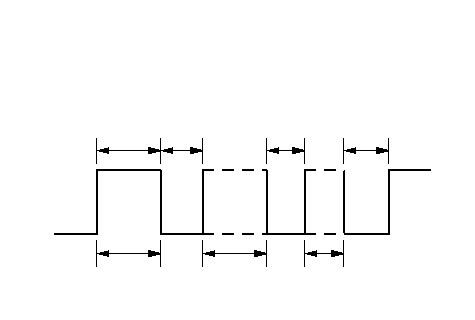 The DTC consists of a main code and sub-code.First emittingMain codeSub-codeS: SecondONOFF6 S3 S2 S3 S
Reading the main code:
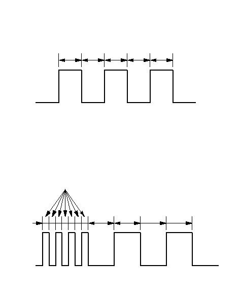 In case of 11~15Four continuous blinks count as 10.Add any further blinks together as shown.Count the number of blinks.In case of 1~10Example:Example:Main code=1+= 311+Main code== 12+101ONOFF0.1 S1.2 S1.2 S1.2 S1.2 S1.2 S1.2 S1.2 S1.2 SONOFF+11.2 S
Reading the sub code:
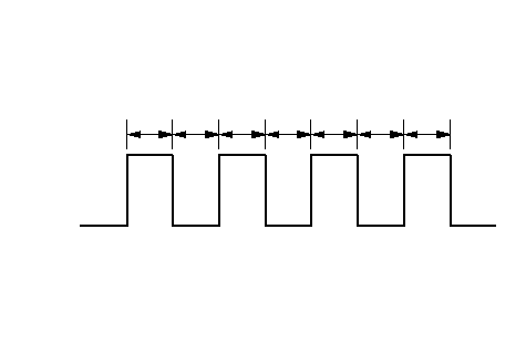 If the main code is '3', and the sub code is '4', record aDTC 3-4.Example:Sub code=+= 4+11+11ONOFF0.3 SCount the number of blinks.0.3 S0.3 S0.3 S0.3 S0.3 S0.3 S
- Including the most recent problem, up to three different malfunctions can be indicated (see example 1 below).
- In case of a continuous failure, the DTC will be indicated repeatedly (see example 1 below).
- In case of an intermittent failure, the SRS indicator will indicate the DTCs one time, then it will stay on (see example 2 below).
- If both a continuous and an intermittent failure occur, both DTCs will be indicated as continuous failures.
- When the system is normal (no DTC), the SRS indicator will stay on (see example 3).
- If the SRS indicator comes on continuously without a DTC, there may be a problem with the system.
- If the SRS indicator does not come on as indicated above, always check for an open or a short to ground in the SCS circuit before troubleshooting the system.
Example of DTC Indications:
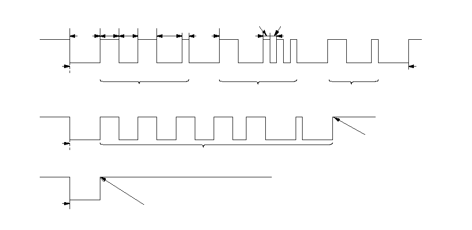 1. Continuous failure, SRS Indicator blinks like this:2. Intermittent failure, SRS Indicator blinks like this:ONOFFBulb check
periodMain code (2)DTC 2-1
Most recent problemSub-code (1)Main code (1)Sub-code (3)DTC 1-3
Second-most recent
problemDTC 1-1
Third-most recent
problemMain code (1)Sub-code (1)Indications
are repeated
in case of
continuous
failure.Indicator stays on in
case of intermittent failure.S: Second3 S1.2 S1.2 S2 S0.3 S3 S0.3S0.3S3. Normal (no failure), SRS Indicator blinks like this:Bulb check
periodBulb check
periodDTC 5-1ONOFFONOFFNo DTC, system is normal, the indicator
stays on.
Erasing the DTC Memory
Special Tools Required
SCS short connector ( 07PAZ-0010100)
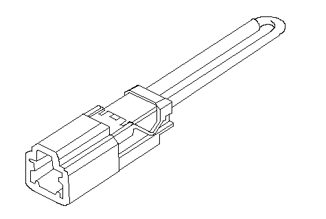
To erase the DTC(s) from the SRS unit, use a Honda PGM Tester (see the Honda PGM Tester SRS vehicle System Supplement) or the following procedure.
| 1. | Make sure the ignition switch is OFF. |
| 2. | Connect the SCS short connector (A) to the MES connector (2P) (B). Do not use a jumper wire.
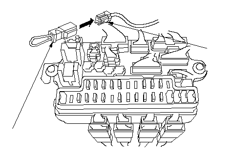 AB AB07PAZ-0010100 |
| 3. | Turn the ignition switch ON (II). |
| 4. | The SRS indicator will come on for about 6 seconds, and then go off. Remove the SCS short connector from the MES connector (2P) within 4 seconds after the indicator goes off. |
| 5. | The SRS indicator will come on again. Reconnect the SCS short connector to the MES connector ( 2P) within 4 seconds after the indicator comes on. |
| 6. | When the SRS indicator goes off, remove the SCS short connector from the MES connector ( 2P) within 4 seconds. |
| 7. | The SRS indicator will blink two times indicating that the memory has been erased. |
| 8. | Turn the ignition switch OFF, and wait for 10 seconds. Turn the ignition switch ON (II) again after the procedure. The SRS system is OK if the SRS indicator comes on for 6 seconds, and then goes off. |
Troubleshooting Intermittent Failures
If there was a malfunction, but it doesn't recur, it will be stored in the memory as an intermittent failure, and the SRS indicator will come on.
After checking the DTC, troubleshoot as follows:
| 1. | Read the DTC (see ‘‘Reading the DTC''). |
| 2. | Erase the DTC memory (see ‘‘Erasing the DTC Memory''). |
| 3. | With the shift lever in Park or neutral, start the engine, and let the engine idle. |
| 4. | The SRS indicator will come on for about 6 seconds and then go off. |
| 5. | Shake the wire harness and the connectors, take a test drive (quick acceleration, quick braking, cornering), turn the steering wheel fully left and right, and hold it there for 5 to 10 seconds. If the problem recurs, the SRS indicator will come on. |
| 6. | If you can't duplicate the intermittent failure, the system is OK at this time. |
Initializing the OPDS (Occupant Position Detection System) Unit
Special Tools Required
SCS short connector ( 07PAZ-0010100)
When the seat-back cover, seat-back cushion, and/or OPDS unit are replaced, initialize the OPDS system by following the procedure below.
NOTE: Make sure the passenger's seat is dry. Set the seat-back in the normal position, and make sure there is nothing on the front passenger's seat.
| 1. | Make sure the ignition switch is OFF. |
| 2. | Connect the DLC pin box (A) to the DLC (16P) (B), and connect the DLC pin box terminals No.4 and No.9 with a jumper wire (C), and push the operation switch. |
| 3. | Connect the SCS short connector (D) to the MES connector (2P) (E). Do not use a jumper wire.
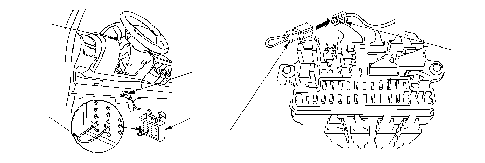 ED ED07PAZ-0010100CFBA |
| 4. | Turn the ignition switch ON (II). |
| 5. | The SRS indicator (F) comes on for about 6 seconds and goes off. Remove the SCS short connector from the MES connector within 4 seconds after the SRS indicator went off. |
| 6. | The SRS indicator comes on again. Reconnect the SCS short connector to the MES connector within 4 seconds after the SRS indicator comes on. |
| 7. | The SRS indicator goes off. Remove the SCS short connector from the MES connector within 4 seconds. |
| 8. | Watch the SRS indicator.
|
| 9. | Turn the ignition switch off, and disconnect the DLC pin box from the DLC (16P).
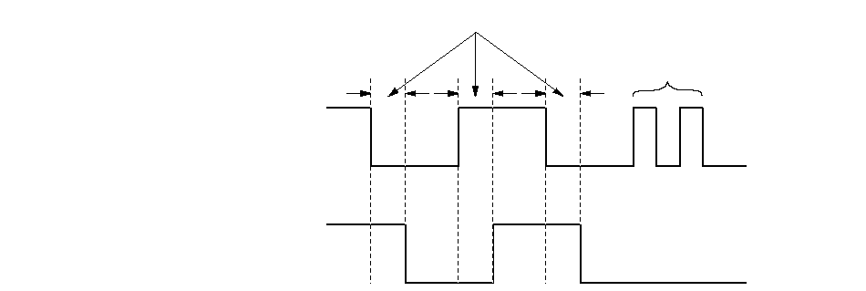 SRS indicator SRS indicator lightMES connector terminalsONOFFCONNECTEDDISCONNECTED4 sec or lessBlinking |