CVT Final Drive Shaft Thrust Clearance Inspection and 25 x 35 mm Thrust Shim Selection
NOTE: If the transmission housing, flywheel housing, final drive shaft, secondary driven gear, or final drive shaft bearing is replaced, select the 25 x 35 mm thrust shim to adjust the final drive shaft thrust clearance.
| 1. | Measure the distance (A) between the flywheel housing surface and bearing inner race surface, then note the measurement (Measurement A).
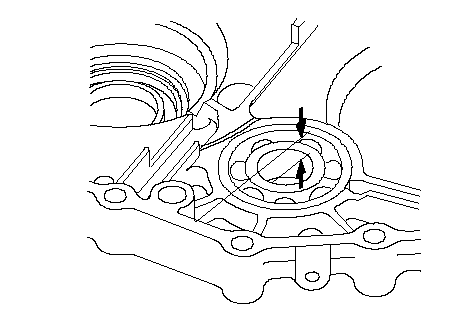 A A 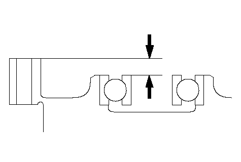 A A |
| 2. | Install the secondary driven gear on the final drive shaft, then install the final drive shaft in the transmission housing.
|
| 3. | Measure the distance (B) between the transmission housing surface and the thrust shim mounting surface on the final drive shaft, then note the measurement (Measurement B).
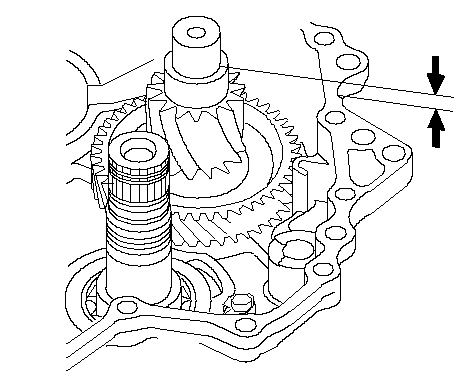 B B 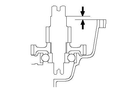 B B |
| 4. | Measure the 25 x 35 mm thrust shim thickness, and check the final drive shaft thrust clearance by calculation from the below formula.
Thrust Clearance Standard:| 0-0.15 mm (0-0.006 in.) |
FORMULA:| Final Drive Shaft Thrust Clearance | | = Measurement A - Measurement B + Flywheel Housing Gasket Thickness (0.5 mm) | | -25 x 35 mm Thrust Shim Thickness (measured) |
|
| 5. | If the clearance is out of standard, select the new 25 x 35 mm thrust shim within the tolerance from the following table.
THRUST SHIM, 25 x 35 mm
| No. | Part Number | Thickness |
|---|
| A | 90551-P4V-000 | 2.8 mm (0.110 in.) | | B | 90552-P4V-000 | 2.9 mm (0.114 in.) | | C | 90553-P4V-000 | 3.0 mm (0.118 in.) | | D | 90554-P4V-000 | 3.1 mm (0.122 in.) | | E | 90555-P4V-000 | 3.2 mm (0.126 in.) | | F | 90556-P4V-000 | 3.3 mm (0.130 in.) | | G | 90557-P4V-000 | 3.4 mm (0.134 in.) | | H | 90558-P4V-000 | 3.5 mm (0.138 in.) | | I | 90559-P4V-000 | 3.6 mm (0.142 in.) | | J | 90560-P4V-000 | 3.7 mm (0.146 in.) | | K | 90561-P4V-000 | 3.8 mm (0.150 in.) | | L | 90562-PWR-000 | 3.9 mm (0.154 in.) | | M | 90563-PWR-000 | 4.0 mm (0.157 in.) | |