Interlock System - Shift Lock System Circuit Troubleshooting (L15A CVT)
Interlock System - Shift Lock System Circuit Troubleshooting
| 1. | Press the brake pedal. Are the brake lights ON? YES - Go to 2. NO - Repair faulty brake pedal circuit.n |
| 2. | Disconnect the battery negative terminal. |
| 3. | Disconnect PCM connectors A (31P) and E (31P). |
| 4. | Connect the battery negative terminal. |
| 5. | Press the brake pedal, and measure the voltage between PCM connector terminals E22 and A23 or A24.
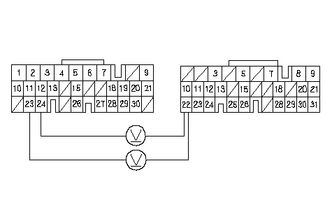 BK SW (WHT/BLK)A (31P)E (31P)PCM CONNECTORSWire side of female terminalsLG2 (BRN/YEL)LG1 (BRN/YEL) BK SW (WHT/BLK)A (31P)E (31P)PCM CONNECTORSWire side of female terminalsLG2 (BRN/YEL)LG1 (BRN/YEL)Is there battery voltage? YES - Release the brake pedal, then go to 6. NO - Repair open in the wire between PCM connector terminal E22 and the brake pedal position switch.n |
| 6. | Turn the ignition switch ON (II). |
| 7. | Press the brake pedal, and measure the voltage between PCM connector terminals E13 and A23 or A24.
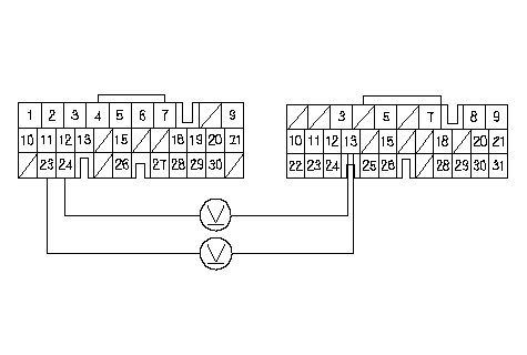 SLC (WHT/BLU)A (31P)E (31P)PCM CONNECTORSWire side of female terminalsLG2 (BRN/YEL)LG1 (BRN/YEL) SLC (WHT/BLU)A (31P)E (31P)PCM CONNECTORSWire side of female terminalsLG2 (BRN/YEL)LG1 (BRN/YEL)Is there battery voltage? YES - Release the brake pedal, then go to 8. NO - Update the PCM if it does not have the latest software, or subsutitute a known-good PCM, then recheck. If the symptom/ indication goes away with a known-good PCM, replace the original PCM.n |
| 8. | Turn the ignition switch OFF. |
| 9. | Disconnect the battery negative terminal. |
| 10. | Connect PCM connectors A (31P) and E (31P). |
| 11. | Connect the battery negative terminal. |
| 12. | Disconnect the gauge assembly connector B (14P). |
| 13. | Turn the ignition switch ON (II). |
| 14. | Press the brake pedal, and measure the voltage between gauge assembly connector terminal B6 and body ground.
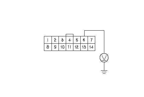 GAUGE ASSEMBLY CONNECTOR B (14P)SLC (WHT/BLU)Wire side of female terminals GAUGE ASSEMBLY CONNECTOR B (14P)SLC (WHT/BLU)Wire side of female terminalsIs there battery voltage? YES - Release the brake pedal, then go to 15. NO - Repair open or short in the wire between PCM connector terminal E13 and the gauge assembly connector terminal B6.n |
| 15. | Turn the ignition switch OFF. |
| 16. | Disconnect the shift lock solenoid/park pin switch connector. |
| 17. | Turn the ignition switch ON (II). |
| 18. | Measure the voltage between shift lock solenoid/park pin switch connector terminal No. 1 and body ground. Do not press the accelerator pedal.
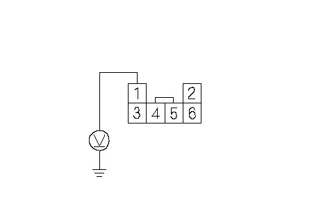 SHIFT LOCK SOLENOID/ SHIFT LOCK SOLENOID/PARK PIN SWITCH CONNECTORIG1 (YEL)Wire side of female terminals Is there battery voltage? YES - Go to 19. NO - Check for blown No. 16 fuse in under-hood fuse/relay box. If the fuse is OK, repair open or short in the wire between the shift lock solenoid connector and the under-hood fuse/relay box.n |
| 19. | Press the brake pedal, and measure the voltage between shift lock solenoid connector terminals No. 1 and No. 3. The shift lever must be in [P] position.
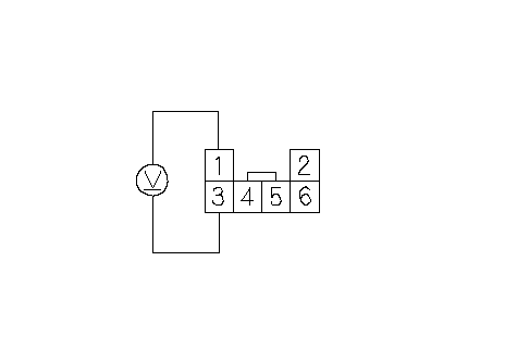 SHIFT LOCK SOLENOID CONNECTORIG1 (YEL)Wire side of female terminalsSHIFT LOCK SOL SHIFT LOCK SOLENOID CONNECTORIG1 (YEL)Wire side of female terminalsSHIFT LOCK SOL(YEL/BLK) Is there battery voltage? YES - Go to 20. NO - Go to 21. |
| 20. | Connect the battery positive terminal to shift lock solenoid/park pin switch connector terminal No. 1, and connect the battery negative terminal to the terminal No. 3, then check that the shift lock solenoid operates. NOTE: Do not connect the battery positive terminal to the terminal No. 3 or you will damage the diode inside the shift lock solenoid.
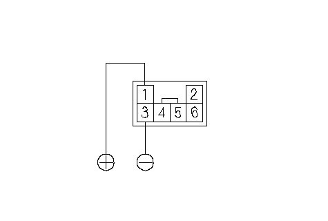 SHIFT LOCK SOLENOID CONNECTOR(RED)Terminal side of male terminals(BLU) SHIFT LOCK SOLENOID CONNECTOR(RED)Terminal side of male terminals(BLU)Does the shift lock solenoid operate properly? YES - Repair the shift lock mechanism.n NO - Replace the shift lock solenoid.n |
| 21. | Turn the ignition switch OFF. |
| 22. | Disconnect gauge assembly connector B (14P). |
| 23. | Check for continuity between gauge assembly connector terminal B1 and shift lock solenoid/park pin switch connector terminal No. 3.
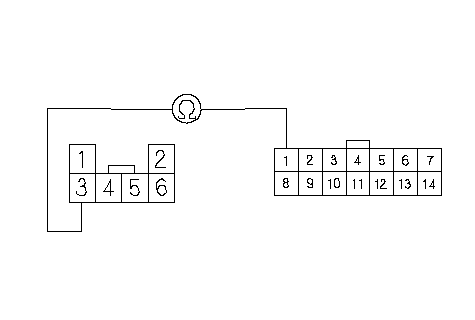 SHIFT LOCK SOLENOID/ SHIFT LOCK SOLENOID/PARK PIN SWITCH CONNECTOR(YEL/BLK)Wire side of female terminals(YEL/BLK)GAUGE ASSEMBLY CONNECTOR B (14P) Is there continuity? YES - Go to 24. NO - Repair open in the wire between gauge assembly connector terminal B1 and the shift lock solenoid/park pin switch connector.n |
| 24. | Check for continuity between gauge assembly connector terminal B14 and body ground while the shift lever is in [P] position, and when the shift lever in any position other than [P] and [N].
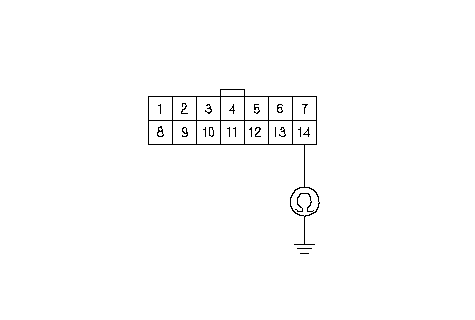 GAUGE ASSEMBLY CONNECTOR B (14P)ATP P (BLK/BLU)Wire side of female terminals GAUGE ASSEMBLY CONNECTOR B (14P)ATP P (BLK/BLU)Wire side of female terminalsIs there continuity while the shift lever is in [P] position, and no continuity when the shift lever in any position other than [P] and [N]? YES - Faulty shift lock system circuit in the gauge assembly, replace the gauge assembly.n NO - Repair open in the ATP P wire between gauge assembly connector terminal B14 and the transmission range switch.n |