Fuel Pump Circuit Troubleshooting (5MT-KG/KE/KR)
Fuel Pump Circuit Troubleshooting
If you suspect a problem with the fuel pump, check that the fuel pump actually runs; when it is ON, you will hear some noise if you listen to the fuel fill port with the fuel fill cap removed. The fuel pump should run for 2 seconds when the ignition switch is first turned on. If the fuel pump does not make noise, check as follows:| 1. | Turn the ignition switch OFF. |
| 2. | Remove the driver's side under cover. |
| 3. | Remove the relay holder (A) from the under-dash fuse/relay box, and remove the PGM-FI main relay 2 (blue) (B) from the relay holder (A), after reinstall the relay holder (A) to the under-dash fuse/relay box.
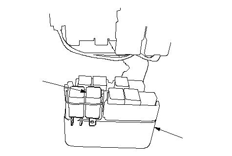 BA BA |
| 4. | Turn the ignition switch ON (II). |
| 5. | Measure voltage between the PGM-FI main relay 2 5P connector terminal No. 3 and body ground.
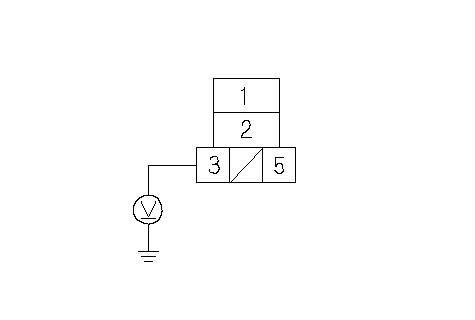 PGM-FI MAIN RELAY 2 PGM-FI MAIN RELAY 25P CONNECTORIGP1 (YEL/BLK)Terminal side of female terminals Is there battery voltage? YES - Go to 6. NO - Repair open in the wire between the PGM-FI main relay 1 and the PGM-FI main relay 2.n |
| 6. | Measure voltage between the PGM-FI main relay 2 5P connector terminal No. 1 and body ground.
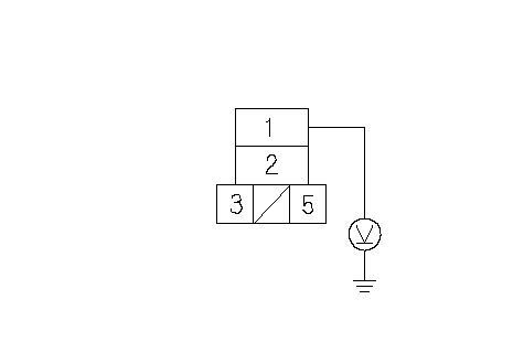 PGM-FI MAIN RELAY 2 PGM-FI MAIN RELAY 25P CONNECTORIG1 (YEL/BLK)Terminal side of female terminals Is there battery voltage? YES - Go to 12. NO - Go to 7. |
| 7. | Turn the ignition switch OFF. |
| 8. | Disconnect the inertia switch 3P connector. |
| 9. | Connect the inertia switch 3P connector terminals No. 1 and No. 3 with a jumper wire.
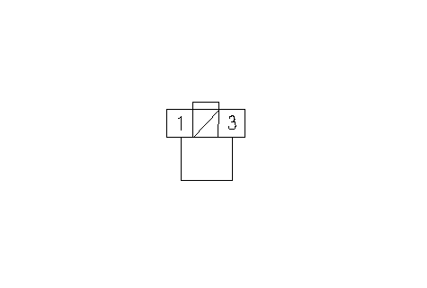 INERTIA SWITCH 3P CONNECTORJUMPER WIREIG1 INERTIA SWITCH 3P CONNECTORJUMPER WIREIG1(BLK/YEL)INERTIA SWITCH (YEL/BLK)Wire side of female terminals |
| 10. | Turn the ignition switch ON (II). |
| 11. | Measure voltage between the PGM-FI main relay 2 5P connector terminal No. 1 and body ground.
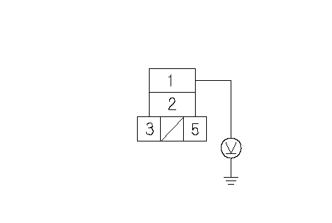 PGM-FI MAIN RELAY 2 PGM-FI MAIN RELAY 25P CONNECTORIG1 (YEL/BLK)Terminal side of female terminals Is there battery voltage? YES - Replace the inertia switch.n NO - Repair open in the wire between the underdash fuse/relay box and PGM-FI main relay 2.n |
| 12. | Turn the ignition switch OFF. |
| 13. | Connect PGM-FI main relay 2 5P connector terminal No. 5 to body ground with a jumper wire.
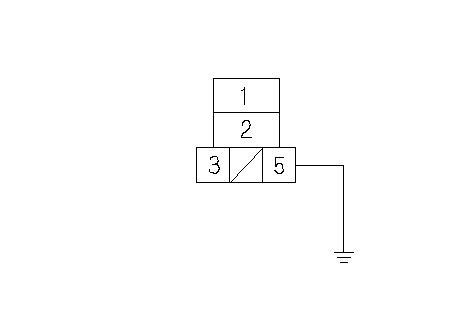 PGM-FI MAIN RELAY 2 PGM-FI MAIN RELAY 25P CONNECTORIMO FPR (GRN/YEL)Terminal side of female terminalsJUMPER WIRE |
| 14. | Wait 10 seconds. |
| 15. | Connect the ECM test harness and test pin box between the ECM and connectors. |
| 16. | Check for continuity between test pin box terminal No. 90 and body ground. Is there continuity? YES - Go to 17. NO - Repair open in the wire between the PGM-FI main relay 2 and ECM connector No. 4 terminal No. 9 (test pin box terminal No. 90).n |
| 17. | Reinstall the PGM-FI main relay 2. |
| 18. | Turn the ignition switch ON (II). |
| 19. | Measure voltage between pin box terminal No. 90 and body ground. Is there battery voltage? YES - Go to 20. NO - Replace the PGM-FI main relay 2.n |
| 20. | Turn the ignition switch OFF. |
| 21. | Turn the ignition switch ON (II), and measure voltage between pin box ternimal No.90 and body ground. Is there battery voltage? YES - Substitute a known-good ECM/PCM and recheck. If symptom/indiction goes away, replace the original ECM/ PCM.n NO - Go to 22. |
| 22. | Turn the ignition switch OFF. |
| 23. | Remove the access panel from the floor. |
| 24. | Measure voltage between the fuel pump 5P connector terminal No. 5 and body ground within the first 2 seconds after the ignition switch was turned ON (II).
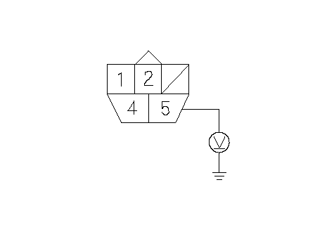 FUEL PUMP 5P CONNECTORFUEL PUMP FUEL PUMP 5P CONNECTORFUEL PUMP (YEL/GRN)Wire side of female terminals Is there battery voltage? YES - Go to 31. NO - Go to 25. |
| 25. | Turn the ignition switch OFF. |
| 26. | Remove the driver's side under cover. |
| 27. | Remove the relay holder (A) from the under-dash fuse/relay box, and remove the PGM-FI main relay 2 (blue) (B) from the relay holder (A), after reinstall the relay holder (A) to the under-dash fuse/relay box.
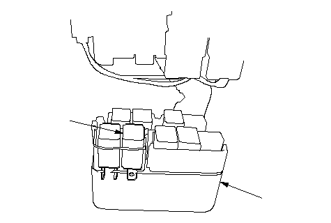 BA BA |
| 28. | Connect the PGM-FI main relay 2 5P connector terminals No. 1 and No. 2 with a jumper wire.
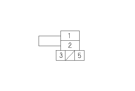 PGM-FI MAIN RELAY 2 PGM-FI MAIN RELAY 25P CONNECTORIG1 (YEL/BLK)Terminal side of female terminalsJUMPER WIREFUEL PUMP (YEL/GRN) |
| 29. | Turn the ignition switch ON (II). |
| 30. | Measure voltage between the fuel pump 5P connector terminal No. 5 and body ground within the first 2 seconds after the ignition switch was turned ON (II).
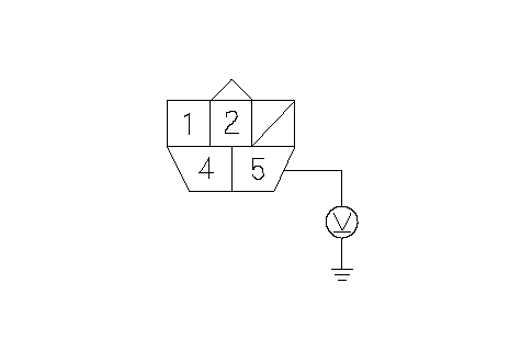 FUEL PUMP 5P CONNECTORFUEL PUMP FUEL PUMP 5P CONNECTORFUEL PUMP (YEL/GRN)Wire side of female terminals Is there battery voltage? YES - Replace the PGM-FI main relay 2.n NO - Repair open in the wire between the PGM-FI main relay 2 and the fuel pump 5P connector.n |
| 31. | Turn the ignition switch OFF. |
| 32. | Check for continuity between the fuel pump 5P connector terminal No. 4 and body ground.
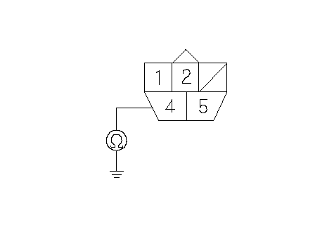 FUEL PUMP 5P CONNECTORGND FUEL PUMP 5P CONNECTORGND (BLK)Wire side of female terminals Is there continuity? YES - Replace the fuel pump.n NO - Repair open in the wire between the fuel pump 5P connector and G402.n |