M/T Countershaft Reassembly (5MT)
M/T Countershaft Reassembly
Exploded View
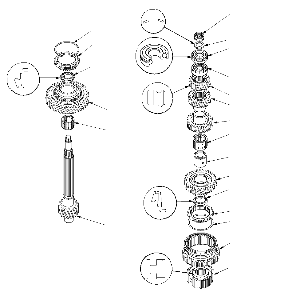 22 mm LOCKNUT
Replace.108 N·m
(11.0 kgf·m,
79.6 lbf·ft)22 mm SPRING WASHERBALL BEARING
Check for wear
and operation.
Note the direction
of installation.BALL BEARING
Check for wear
and operation.5TH GEAR4TH GEAR3RD GEARNEEDLE BEARING
Check for wear
and operation.DISTANCE COLLAR2ND GEARSYNCHRO RINGREVERSE GEAR1ST/2ND
SYNCHRO HUBSYNCHRO SPRING1ST GEARNEEDLE BEARING
Check for wear
and operation.COUNTERSHAFTFRICTION DAMPER
Check for wear
and operation.SYNCHRO SPRINGFRICTION DAMPER
Check for wear
and operation.SYNCHRO RING
Special Tools Required
Driver, 40 mm I.D. ( 07746-0030100)
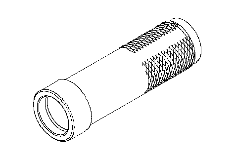
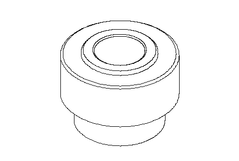
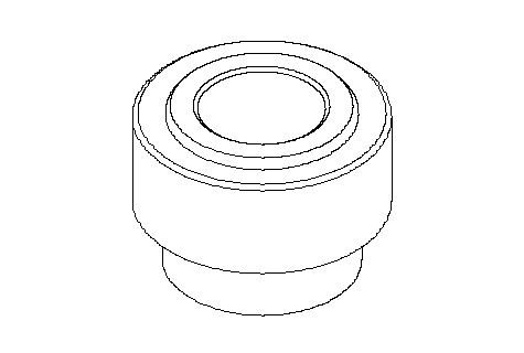
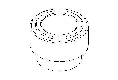
NOTE: Refer to the Exploded View, as needed during this procedure.
| 1. | Clean all the parts in solvent, dry them, and apply lubricant all contact surfaces. |
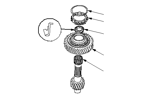
| 2. | Install the needle bearing (A), 1st gear (B), and friction damper (C) on the shaft. |
| 3. | Install the 1st gear synchro ring (D) and synchro spring (E) on the shaft.
 EDCBA EDCBA |
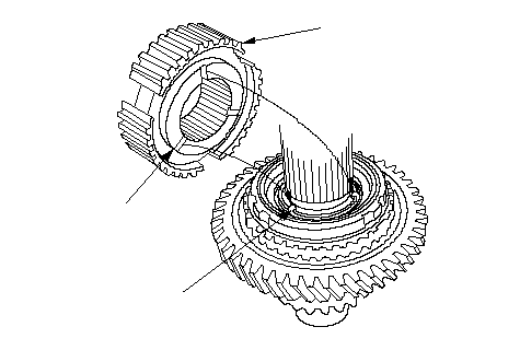
| 4. | Align the fingers (A) on the friction damper with the grooves (B) on the 1st/2nd synchro hub (C), then install the 1st/2nd synchro hub onto the shaft.
 ABC ABC |
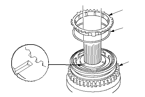
| 5. | Install the reverse gear (A), synchro spring (B), and synchro ring (C) on the shaft.
 CBA CBA |
| 6. | Install the distance collar (A) and friction damper (B), then align the fingers (C) on the friction damper and grooves (D) in the 1st/2nd synchro hub.
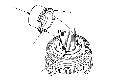 BACD BACD |
| 7. | Install the needle bearing (A) and 2nd gear (B).
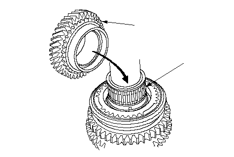 BA BA |
| 8. | Install the 3rd gear (A) using the special tools and a press (B).
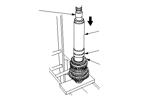 07746-003010007746-0030400AB 07746-003010007746-0030400AB |
| 9. | Install the 4th gear (A) using the special tools and a press (B).
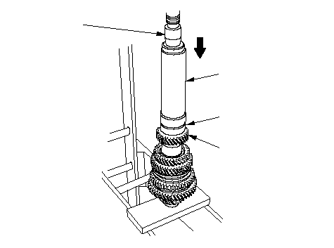 07746-003010007746-0030300AB 07746-003010007746-0030300AB |
| 10. | Install the 5th gear (A) using the special tools and a press (B).
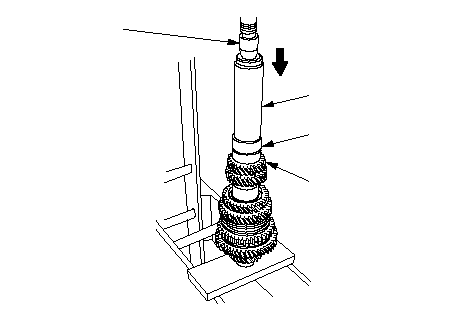 07746-003010007746-0030300AB 07746-003010007746-0030300AB |
| 11. | Install the ball bearing (A) using the special tools and a press (B).
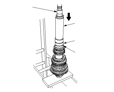 07746-003010007746-0030200AB 07746-003010007746-0030200AB |
| 12. | Install the ball bearing (A) using the special tools and a press (B).
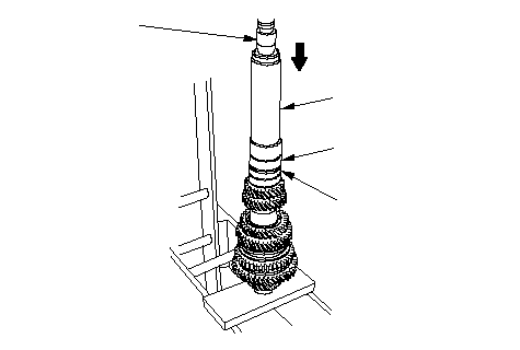 07746-003010007746-0030200AB 07746-003010007746-0030200AB |
| 13. | Install the 22 mm spring washer (A) and 22 mm locknut (left-hand threads) (B).
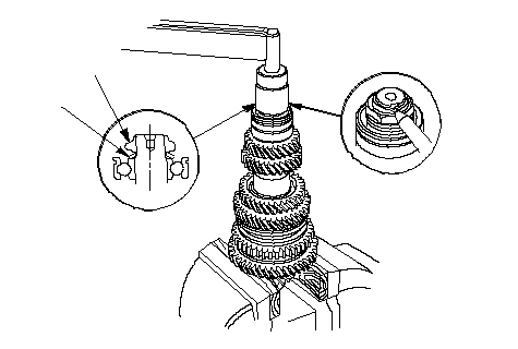 BA BA |
| 14. | Securely clamp the countershaft assembly in a bench vise with wood blocks. |
| 15. | Torque the new locknut to 108 N·m (11.0 kgf·m, 79.6 lbf·ft), then loosen it and torque it again to the same value. Stake the locknut tab into the groove. |