Driveshaft Disassembly
Special Tools Required
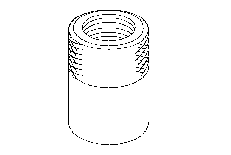
Threaded adapter, 22 x 1.5 mm ( 07XAC-0010100)
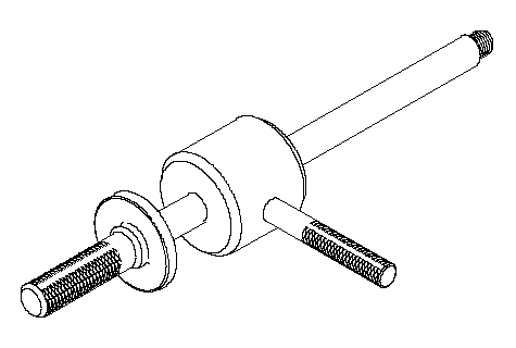
Slide hammer ( 07936-5790001)
Boot band pincers (, commercially available)
Inboard Joint Side:
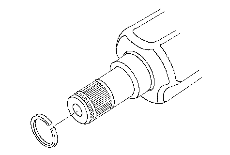
| 1. | Remove the set ring from the inboard joint.
|
| 2. | Remove the boot bands. Be careful not to damage the boot and dynamic damper.
- If the boot band is a double loop type (A), lift up the band bend (B), and push it into the clip (C).
- If the boot band is a low profile type (D), lift up the two tabs (E) with a screwdriver and pinch the boot band using the commercially available boot band pincer (F).
- If the boot band is an ear clamp type (G), lift up the three tabs (H) with a screwdriver.
Double Loop Type 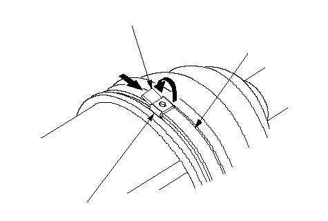 BAC BACLow Profile Type 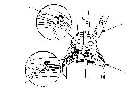 EFDE EFDE
Ear Clamp Type 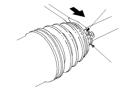 GH GH |
| 3. | Make a mark (A) on each roller (B) and inboard joint (C) to identify the locations of rollers and grooves in the inboard joint. Then remove the inboard joint on the shop towel (D). Be careful not to drop the rollers when separating them from the inboard joint.
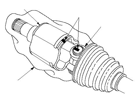 CDAB CDAB |
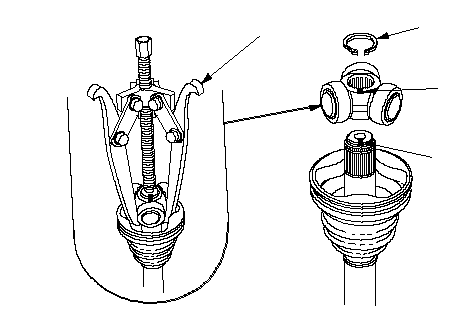
| 4. | Remove the circlip (A).
 DABC DABC |
| 5. | Mark the spider (B) and right driveshaft (C) to identify the position of the spider on the shaft.
|
| 6. | Remove the spider and rollers using a commercially available bearing remover (D).
|
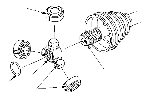
| 7. | Make a mark (A) on the rollers (B) and spider (C) to identify the locations of the rollers on the spider, then remove the rollers.
 BEADC BEADC |
| 8. | Remove the circlip (D).
|
| 9. | Mark the spider (C) and left driveshaft (E) to identify the position of the spider on the shaft.
|
| 10. | Remove the spider (C).
|
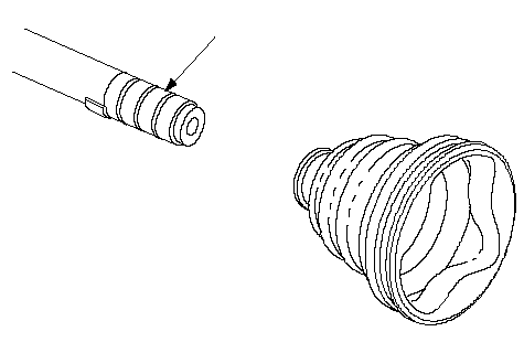
| 11. | Wrap the splines on the driveshaft with vinyl tape (A) to prevent damage to the boot.
 A A |
| 12. | Remove the inboard boot. Be careful not to damage the boot.
|
| 13. | Remove the vinyl tape.
|
Outboard Joint Side:
| 1. | Remove the boot bands. Be careful not to damage the boot and dynamic damper.
If the boot band is an ear clamp type (A), lift up the three tabs (B) with a screwdriver.
Ear Clamp Type 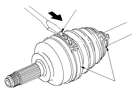 BA BA |
| 2. | Slide the outboard boot (A) partially to the inboard joint side. Be careful not to damage the boot.
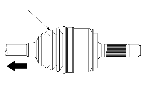 A A |
| 3. | Wipe off the grease to expose the driveshaft and the outboard joint inner race.
|
| 4. | Make a mark (A) on the driveshaft (B) at the same position of the outboard joint end (C).
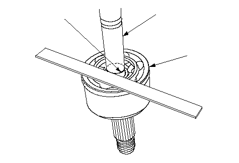 ABC ABC |
| 5. | Carefully clamp the driveshaft in a vise.
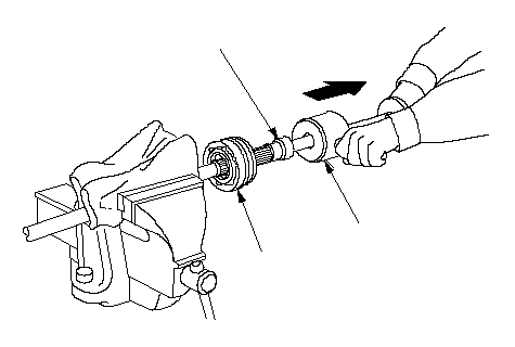 07XAC-001010007936-5790001A 07XAC-001010007936-5790001A |
| 6. | Remove the outboard joint (A) using the special tool.
|
| 7. | Remove the driveshaft from the vise.
|
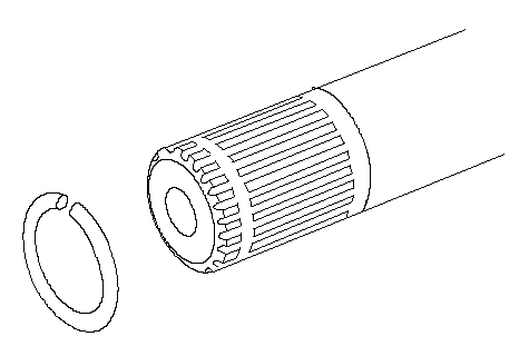
| 8. | Remove the stop ring from the driveshaft.
|
| 9. | Wrap the splines on the driveshaft with vinyl tape (A) to prevent damage to the boot.
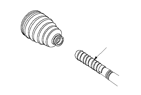 A A |
| 10. | Remove the outboard boot. Be careful not to damage the boot.
|
| 11. | Remove the vinyl tape.
|