DLC Circuit Troubleshooting (With ETCS)
DLC Circuit Troubleshooting
NOTE:
- If the ECM/PCM does not communicate with the HDS, do this troubleshooting procedure.
- Check that MIL circuit is normal, then do this troubleshooting.
| 1. | Measure voltage between DLC terminal No. 16 and body ground.
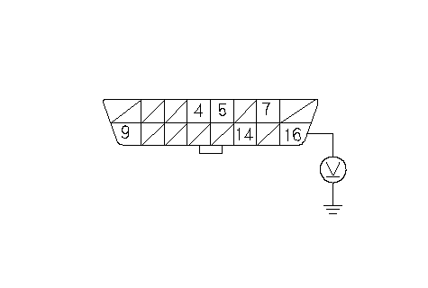 DATA LINK CONNECTOR (DLC)Terminal side of female terminals+B DATA LINK CONNECTOR (DLC)Terminal side of female terminals+B(WHT/RED) Is there battery voltage? YES - Go to 2. NO - Repair open in the wire between DLC terminal No. 16 and the No. 8 (15A) fuse in the under-hood fuse/relay box.n |
| 2. | Measure voltage between DLC terminals No. 4 and No. 16.
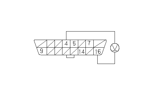 DATA LINK CONNECTOR (DLC)Terminal side of female terminals+B (WHT/RED)GND (BLK) DATA LINK CONNECTOR (DLC)Terminal side of female terminals+B (WHT/RED)GND (BLK)Is there battery voltage? YES - Go to 3. NO - Repair open in the wire between DLC terminal No. 4 and body ground (G402).n |
| 3. | Measure voltage between DLC terminals No. 5 and No. 16.
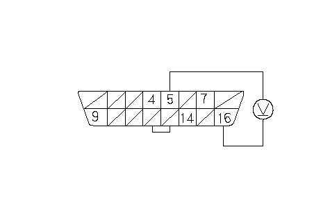 DATA LINK CONNECTOR (DLC)Terminal side of female terminals+B (WHT/RED)LG3 (BRN/YEL) DATA LINK CONNECTOR (DLC)Terminal side of female terminals+B (WHT/RED)LG3 (BRN/YEL)Is there battery voltage? YES - Go to 4. NO - Repair open in the wire between the ECM connector No. 1 terminal No. 8 (test pin box terminal No. 8) and DLC terminal No. 5.n |
| 4. | Turn the ignition switch ON (II). |
| 5. | Measure voltage between DLC terminals No. 5 and No. 7.
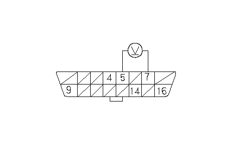 DATA LINK CONNECTOR (DLC)Terminal side of female terminalsLG3 DATA LINK CONNECTOR (DLC)Terminal side of female terminalsLG3(BRN/YEL)K-LINE (RED/WHT) Is there 8.5 V or more? YES - Go to 10. NO - Go to 6. |
| 6. | Turn the ignition switch OFF, and wait 10 seconds. |
| 7. | Connect the ECM test harness and the test pin box to the wire harness only, not to the ECM. |
| 8. | Check for continuity between DLC terminal No. 7 and body ground.
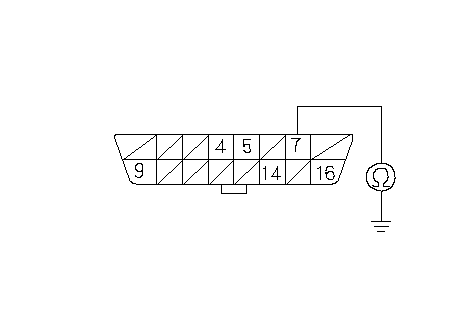 DATA LINK CONNECTOR (DLC)Terminal side of female terminalsK-LINE DATA LINK CONNECTOR (DLC)Terminal side of female terminalsK-LINE(RED/WHT) Is there continuity? YES - Repair short in the wire between the ECM connector No. 4 terminal No. 5 (test pin box terminal No. 86) and DLC terminal No. 7. After repairing the wire, check for a DTC with the HDS. If any Temporary DTCs or DTCs are indicated, go to the indicated DTC troubleshooting.n NO - Go to 9. |
| 9. | Check for continuity between the test pin box terminal No. 86 and DLC terminal No. 7.
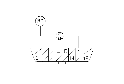 DATA LINK CONNECTOR (DLC)Terminal side of female terminalsK-LINE DATA LINK CONNECTOR (DLC)Terminal side of female terminalsK-LINE(RED/WHT)TEST PIN BOX TERMINAL Is there continuity? YES - Substitute a known-good ECM, then recheck. If the symptom/indication goes away, replace the original ECM.n NO - Repair open in the wire between the ECM connector No. 4 terminal No. 5 (test pin box terminal No. 86) and DLC terminal No. 7. After repairing the wire, check for a DTC with the HDS. If any Temporary DTCs or DTCs are indicated, go to the indicated DTC troubleshooting.n |
| 10. | Turn the ignition switch OFF, and wait 10 seconds. |
| 11. | Connect the ECM test harness and the test pin box to the wire harness only, not to the ECM. |
| 12. | Turn the ignition switch ON (II). |
| 13. | Measure voltage between DLC terminals No. 5 and No. 7.
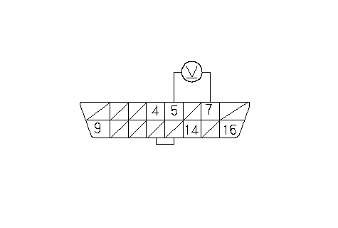 DATA LINK CONNECTOR (DLC)Terminal side of female terminalsLG3 DATA LINK CONNECTOR (DLC)Terminal side of female terminalsLG3(BRN/YEL)K-LINE (RED/WHT) Is there 0 V? YES - Substitute a known-good ECM, then recheck. If the symptom/indication goes away, replace the original ECM.n NO - Repair short to power in the wire between the ECM connector No. 4 terminal No. 5 (test pin box terminal No. 86) and DLC terminal No. 7. After repairing the wire, check for a DTC with the HDS. If any DTCs or DTCs are indicated, go to the indicated DTC troubleshooting.n |