EPS Indicator Circuit Troubleshooting (HATC Model)
EPS Indicator Circuit Troubleshooting
| 1. | Turn the ignition switch ON (II), start the engine and watch the EPS indicator. Does the EPS indicator come on? YES - If the EPS indicator comes on and goes off, it's OK. If the EPS indicator stays on blinks, alway check for an open or a short to ground in the SCS circuit. NO - Go to 2. |
| 2. | Turn the ignition switch OFF, then ON (II) again and watch the brake system indicator. Does the brake system indicator come on? YES - Go to 3. NO - Repair open in the indicator power source circuit:n
|
| 3. | Turn the ignition switch OFF. |
| 4. | Disconnect the gauge assembly 20P connector. |
| 5. | Turn the ignition switch ON (II). |
| 6. | Measure the voltage between the gauge assembly 20P connector terminal No. 2 and body ground.
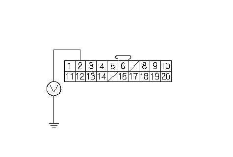 GAUGE ASSEMBLY 20P CONNECTORIG1 (YEL)Wire side of female terminals GAUGE ASSEMBLY 20P CONNECTORIG1 (YEL)Wire side of female terminalsIs there battery voltage? YES - Go to 7. NO - Repair open in the wire between the gauge assembly and No. 3 METER (7.5 A) fuse.n |
| 7. | Turn the ignition switch OFF. |
| 8. | Connect the gauge assembly 20P connector on the gauge assembly. |
| 9. | Turn the ignition switch ON (II). |
| 10. | Connect the gauge assembly 30P connector terminal No. 26 to body ground with a jumper wire.
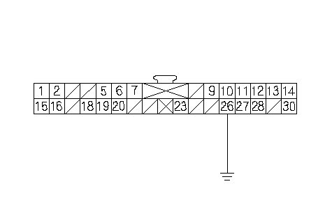 GAUGE ASSEMBLY 30P CONNECTORWLP GAUGE ASSEMBLY 30P CONNECTORWLP(YEL/RED)Wire side of female terminalsJUMPER WIRE Does EPS indicator come on? YES - Go to 11. NO - Faulty gauge assembly.n |
| 11. | Turn the ignition switch OFF. |
| 12. | Disconnect the negative cable from the battery. |
| 13. | Disconnect the EPS control unit connector B (14P). |
| 14. | Reconnect the negative cable to the battery. |
| 15. | Turn the ignition switch ON (II). |
| 16. | Connect the EPS control unit connector B (14P) terminal No. 13 to body ground with a jumper wire.
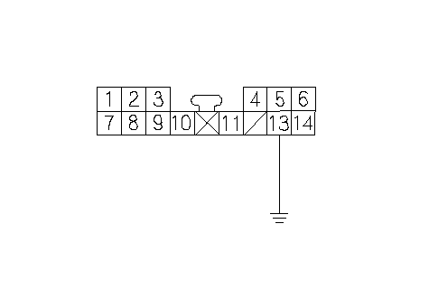 EPS CONTROL UNIT CONNECTOR B (14P)WLP (YEL/RED)Wire side of female terminalsJUMPER EPS CONTROL UNIT CONNECTOR B (14P)WLP (YEL/RED)Wire side of female terminalsJUMPERWIRE Does EPS indicator come on? YES - Go to 17. NO - Repair open in the wire between the gauge assembly and EPS control unit.n |
| 17. | Turn the ignition switch OFF. |
| 18. | Disconnect the negative cable from the battery. |
| 19. | Disconnect the EPS control unit connector A (4P). |
| 20. | Check for continuity between body ground and the EPS control unit connector A (4P) terminal No. 4 to body ground.
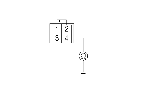 EPS CONTROL UNIT CONNECTOR A (4P)Wire side of female terminalsGND EPS CONTROL UNIT CONNECTOR A (4P)Wire side of female terminalsGND(BLK) Is there continuty? YES - Go to 21. NO - Repair open in the wire between the EPS control unit and body ground (G451).n |
| 21. | Reconnect the negative cable to the battery. |
| 22. | Turn the ignition switch ON (II). |
| 23. | Measure the voltage between the EPS control unit connector B (14P) terminal No. 6 and body ground.
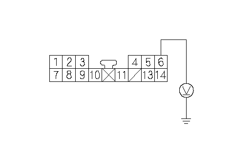 EPS CONTROL UNIT CONNECTOR B (14P)IG1 (YEL)Wire side of female terminals EPS CONTROL UNIT CONNECTOR B (14P)IG1 (YEL)Wire side of female terminalsIs there battery voltage? YES - Go to 24. NO - Repair open in the wire between the EPS control unit connector B (14P) and No. 3 METER (7.5 A) fuse.n |
| 24. | Turn the ignition switch OFF. |
| 25. | Reconnect the EPS control unit connectors A and B. |
| 26. | Turn the ignition switch ON (II). Does EPS indicator come on? YES - The system is OK at this time.n NO - Check for loose EPS control unit connectors. If necessary, substitute a known-good EPS control unit and recheck.n |