SRS System Description
SRS System Description
SRS Components
Airbags
The SRS is a safety device which, when used with the seat belt, is designed to help protect the driver and front passenger in a frontal impact exceeding a certain set limit. The system consists of the SRS unit, including safing sensor and impact sensor (A), the cable reel (B), the driver's airbag (C), the front passenger's airbag (D), side airbags (E), seat belt tensioners (I), seat belt outer lap tensioners (J) and front impact sensors (K).Side Airbags
The side airbags (E) are in each front seat-back. They help protect the upper torso of the driver or front seat passenger during a moderate to severe side impact. Side impact sensors (L) in each door sill and in the SRS unit detect such an impact and instantly inflate the driver's or the passenger's side airbag. Only one side airbag will deploy during a side impact. If the impact is on the passenger's side, the passenger's side airbag will deploy even if there is no passenger.Seat Belt Tensioners/Seat Belt Outer Lap Tensioners
The seat belt tensioners are linked with the SRS airbags to further increase the effectiveness of the seat belt. In a front-end collision, the tensioners instantly retract the belt firmly to secure the occupants in their seats.
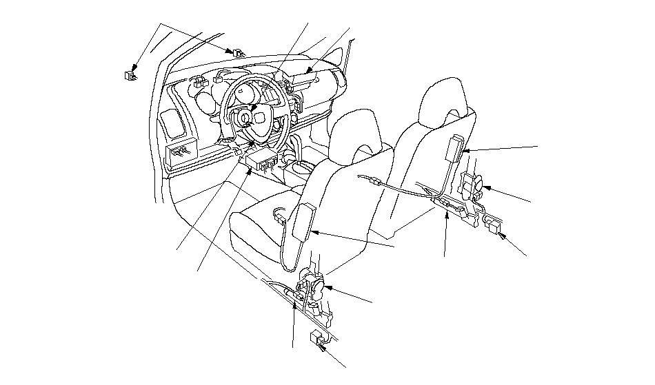 ACDEKJLIDBJLIE
SRS Operation
The main circuit in the SRS unit senses and judges the force of impact and, if necessary, ignites the inflator charges. If battery voltage is too low or power is disconnected due to the impact, the voltage regulator and the back-up power circuit, respectively, will keep voltage at a constant level.For the SRS to operate
Driver's and Front Passenger's Airbag(s)
(1) The front impact sensor must activate, and send electric signals to the microprocessor.(2) The microprocessor must compute the signals, and depending on the severity of the collision and whether the seat belt buckle switch is ON or OFF, it sends the appropriate signals to the airbag inflator(s).
(3) The inflators that received signals must ignite and deploy the airbag (s).
Side Airbag(s)
(1) The side impact sensors must activate, and send electric signals to the microprocessor.
(2) The microprocessor must compute the signals and send them to the side airbag inflator(s). However, the microprocessor cuts off the signals to the front passenger's side airbag if the SRS unit determines that the front passenger's head is in the deployment path of the side airbag.
(3) The inflator that received the signal must ignite and deploy the side airbag.
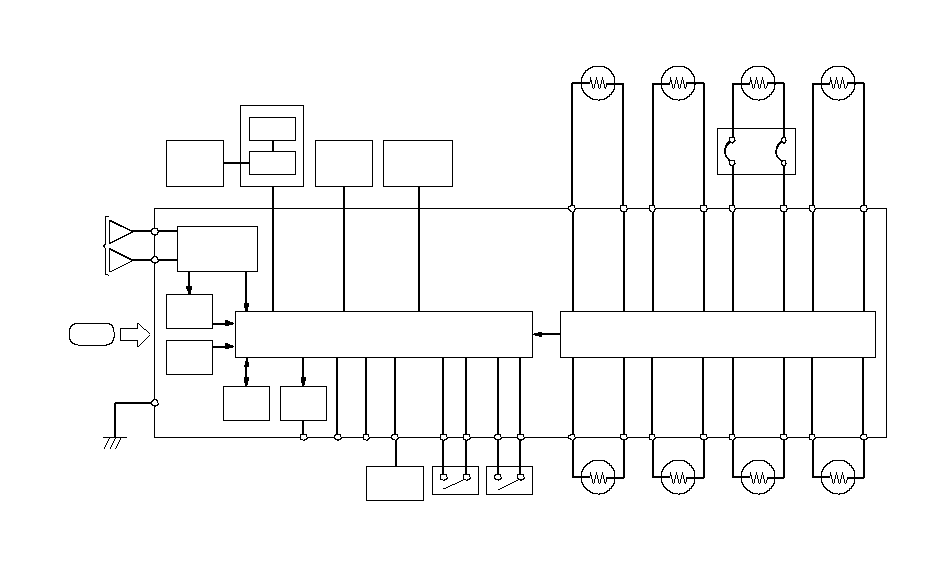 REELMICROPROCESSOR and DIAGNOSTIC CIRCUITCABLESRS UNITIMPACTGNDTRIGGER CIRCUITIDCSCSMESDLCVAVBUNDER-DASH
 FUSE/RELAY
BOXSIDE
AIRBAG
CUTOFF
INDICATORFRONT
PASSENGER'S
SEATOPDS
SENSOROPDS
UNITDRIVER'S
SIDE IMPACT
SENSORFRONT
PASSENGER'S
SIDE IMPACT
SENSORPOWER SUPPLY
CIRCUITFRONTAL
IMPACT
SENSORSIDE
IMPACT
SENSORMEMORY
CIRCUITDATA
LINK
CIRCUITSRS
INDICATORLEFT
FRONT
SENSORRIGHT
FRONT
SENSORLEFT SIDE
SEAT BELT
TENSIONERRIGHT SIDE
SEAT BELT
TENSIONERLEFT SIDE
SEAT BELT
OUTER LAP
TENSIONERRIGHT SIDE
SEAT BELT
OUTER LAP
TENSIONERFRONT
PASSENGER'S
AIRBAG
INFLATORDRIVER'S
AIRBAG
FIRST
INFLATORDRIVER'S
SIDE AIRBAG
INFLATORFRONT
PASSENGER'S
SIDE AIRBAG
INFLATOR
Self-diagnosis System
A self-diagnosis circuit is built into the SRS unit; when the ignition switch is turned ON (II), the SRS indicator light comes on and goes off after about 6 seconds if the system is operating normally.If the light does not come on, or does not go off after 6 seconds, or if it comes on while driving, it indicates an abnormality in the system. The system must be inspected and repaired as soon as possible.
For better serviceability, the SRS unit memory stores a DTC that relates to the cause of the malfunction, and the unit is connected to the data link connector (DLC). This information can be read with the HDS when it is connected to the DLC (16P).