CVT Reassembly
Special Tools Required
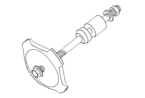
Reverse brake spring compressor ( 07TAE-P4V0110)
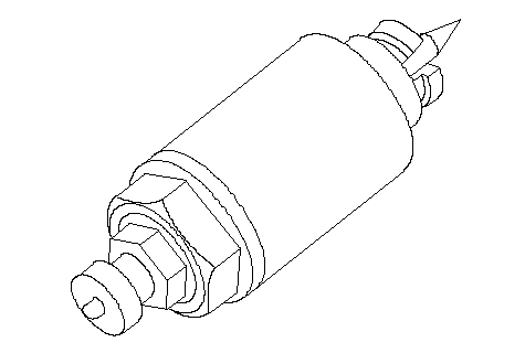
Start clutch installer ( 07TAE-P4V0130)
| 1. | Soak the reverse brake discs thoroughly in ATF for a minimum of 30 minutes.
|
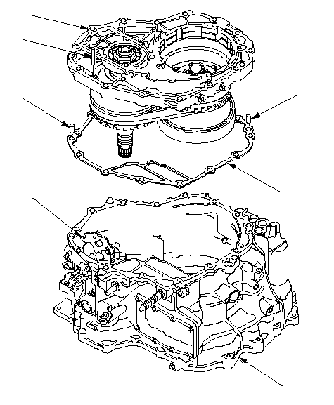
| 2. | Install the dowel pins (2) (A) and the new gasket (B) on the transmission housing (C).
 DAEACBF DAEACBF |
| 3. | Push the control shaft (D) toward the outside of the transmission housing, then install the intermediate housing (E).
|
| 4. | Put the control shaft back, then install the roller (F) in the intermediate housing with aligning the groove on the control shaft.
|
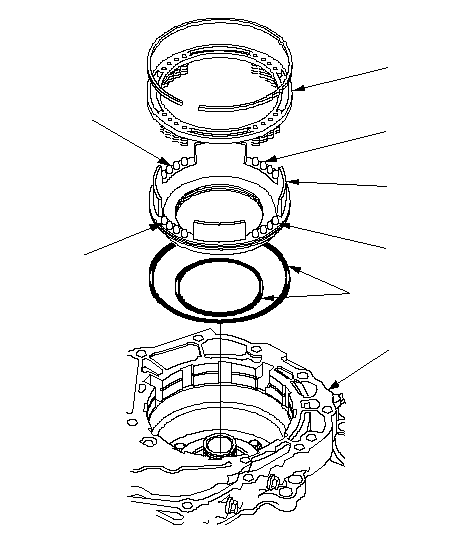
| 5. | Install the new O-rings (A) on the reverse brake piston (B), then install the piston in the intermediate housing (C).
 DAECBEEE DAECBEEE |
| 6. | Install the spring retainer/return spring assembly (D); install the return springs on the spring guide (E) on the reverse brake piston.
|
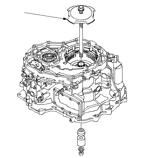
| 7. | Install the special tool through the drive pulley shaft to compress the return spring. Be sure the special tool (spring compressor attachment) is set over the return springs, not to over the reverse brake piston.
 07TAE-P4V0110 07TAE-P4V0110 |
| 8. | Compress the return springs with making sure that the special tool set over the return springs and the spring retainer tabs does not ride on the reverse brake piston.
|
| 9. | Install the snap ring in the intermediate housing above the spring retainer, and remove the special tool.
|
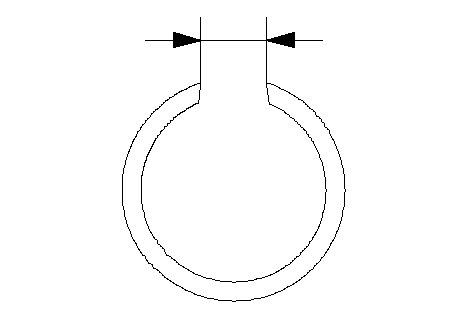
| 10. | Verify that the snap ring end gap (A) is 15 mm (0.59 in.) and above.
 A A |
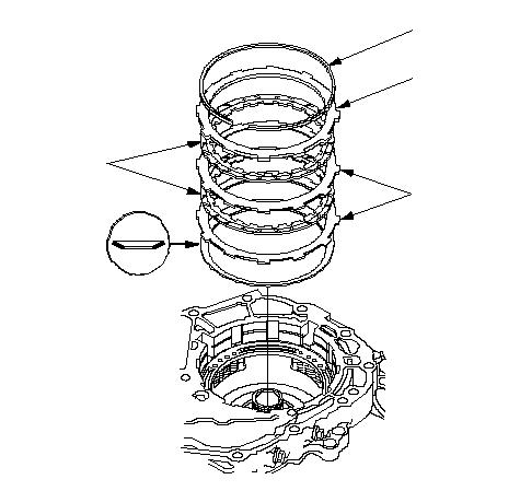
| 11. | Install the disc spring (A) on the reverse brake piston in the direction shown.
 EDBCA EDBCA |
| 12. | Starting with the reverse brake plate (B), alternately install the plates and discs (C). Install the reverse brake end plate (D), then install the snap ring (E).
|
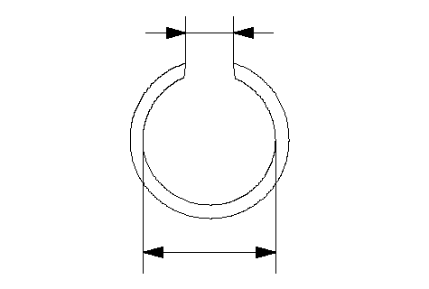
| 13. | Verify that the snap ring inside diameter (A) is 143.5 mm (5.65 in.) and above, and also the snap ring end gap (B) is 18 mm (0.71 in.) and above.
 AB AB |
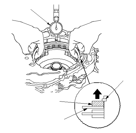
| 14. | Set a dial indicator (A) on the reverse brake and plate (B).
 ABCD ABCD |
| 15. | Zero the dial indicator with lifting the top disc (C) up to contact the reverse brake end plate to the snap ring (D).
|
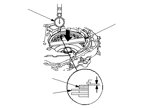
| 16. | Release the end plate to lower the end plate, and place a steel plate across width of the reverse brake end plate.
|
| 17. | Press the steel plate (A) down with 40 N (4 kgf, 9 lbf) using a force gauge, and read the dial indicator (B). The dial indicator reads the clearance (C) between the reverse brake end plate (D) and top disc (E). Take measurements in at least three places, and use the average as the actual clearance.
| Standard: | 0.70-0.85 mm (0.028-0.033 in.) |
 ABCDE40 N ABCDE40 N
(4 kgf, 9 lbf) |
| 18. | If the clearance is out of standard, select a new reverse brake end plate from the following table.
REVERSE BRAKE END PLATE| Plate No. | Part Number | Thickness |
|---|
| 1 | 22551-P4V-003 | 3.6 mm (0.142 in.) | | A | 22551-PWR-000 | 3.7 mm (0.146 in.) | | 2 | 22552-P4V-003 | 3.8 mm (0.150 in.) | | B | 22553-PWR-000 | 3.9 mm (0.154 in.) | | 3 | 22553-P4V-003 | 4.0 mm (0.157 in.) | | C | 22553-PWR-000 | 4.1 mm (0.161 in.) | | 4 | 22554-P4V-003 | 4.2 mm (0.165 in.) | | D | 22554-PWR-000 | 4.3 mm (0.169 in.) | | 5 | 22555-P4V-003 | 4.4 mm (0.173 in.) | | E | 22555-PWR-000 | 4.5 mm (0.177 in.) | | 6 | 22556-P4V-003 | 4.6 mm (0.181 in.) | | F | 22556-PWR-000 | 4.7 mm (0.185 in.) | | 7 | 22557-P4V-003 | 4.8 mm (0.189 in.) | | 8 | 22558-P4V-003 | 5.0 mm (0.200 in.) |
|
| 19. | If replacing the reverse brake end plate, make sure that the clearance is within the tolerance.
|
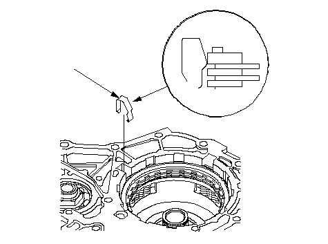
| 20. | Select and install the reverse brake end plate spring (A).
 A AREVERSE BRAKE END PLATE SPRING| Reverse Brake Discs | Part Number | Discernment Color |
|---|
| 2 discs | 22549-PWR-000 | White | | 3 discs | 22549-PWR-900 | Light Blue | |
| 21. | Install the snap ring retainer (A) over the drive pulley shaft (B).
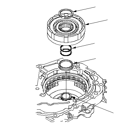 EDCAB EDCAB |
| 22. | Wrap the drive pulley shaft splines with tape to prevent O-ring damage. Install the new O-rings (C) in the drive pulley shaft O-ring grooves, then remove the tape.
|
| 23. | Install the forward clutch (D) on the drive pulley shaft, then install the snap ring (E) to secure the forward clutch.
|
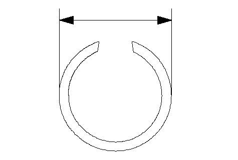
| 24. | Verify that the snap ring outside diameter (A) is 41.4 mm (1.63 in.) or less.
 A A |
| 25. | Install the ring gear (A) on the forward clutch (B).
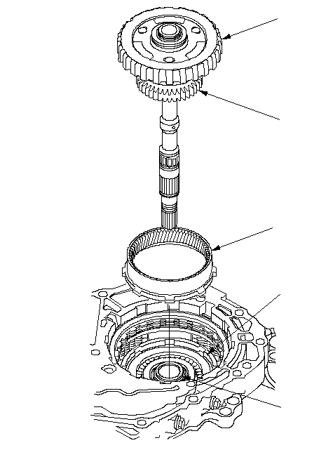 EDCAB EDCAB |
| 26. | Install the input shaft/planetary carrier assembly (C) through the drive pulley shaft (D) with aligning the sun gear (E) to the forward clutch discs and aligning the planetary carrier to the reverse brake discs.
|
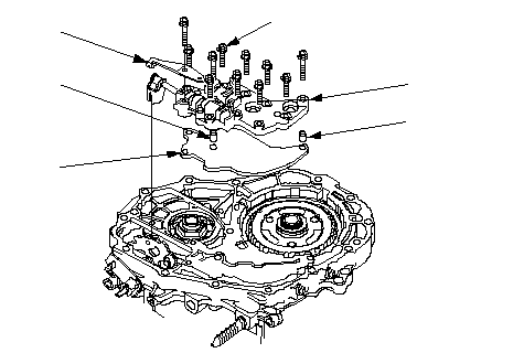
| 27. | Install the manual valve body separator plate (A) and dowel pins (2) (B) on the intermediate housing, then install the manual valve body (C) and detent spring (D).
 6 x 1.0 mm 6 x 1.0 mm
12 N·m (1.2 kgf·m, 8.7 lbf·ft)DCABB |
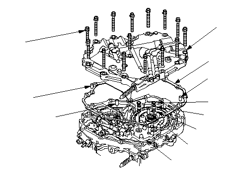
| 28. | Install the new O-rings (A) on the 10.9 mm ATF pipes (2) (B), then install the ATF pipes on the manual valve body (C).
 8 x 1.25 mm 8 x 1.25 mm
34 N·m (3.5 kgf·m,
25 lbf·ft)DCABGFEEDA |
| 29. | Install the 8 mm ATF pipes (2) (D) on the manual valve body.
|
| 30. | Install the dowel pins (2) (E) and the new gasket (F) on the intermediate housing, then install the end cover (G).
|
| 31. | Turn the transmission end cover down.
|
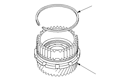
| 32. | Install the sealing ring (A) on the new secondary drive/park gear (B).
 BA BA |
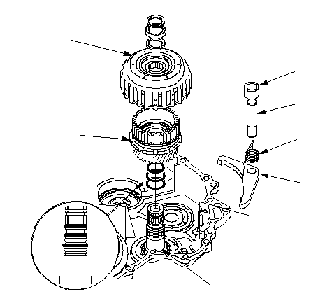
| 33. | Install the park pawl (A), pawl spring (B), pawl shaft (C), and shaft sleeve (D) on the transmission housing, then move the control lever to any position other than [P].
 FGHDCBAE FGHDCBAE |
| 34. | Wrap the driven pulley shaft splines to prevent O-ring damage, install the new O-ring (E) in the shaft O-ring grooves, and remove the tape.
|
| 35. | Install the secondary drive/park gear (F) in the start clutch (G), then install them on the driven pulley shaft (H).
|
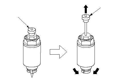
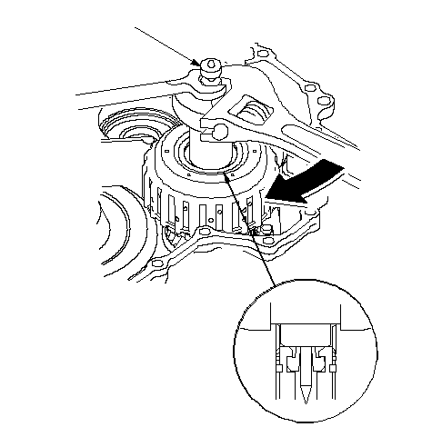
| 36. | Pull the handle (A) of the special tool up, then install the tip of it into the driven pulley shaft feed pipe hole, and set the special tool on the start clutch. Do not allow dirt or other particles to enter into the transmission.
 07TAE-P4V0130A 07TAE-P4V0130A |
| 37. | Push the handle (A) of the special tool, then tighten the nut to seat the secondary drive/park gear on the drive pulley shaft.
 A A |
| 38. | Pull the handle of the special tool up, and remove the special tool.
|
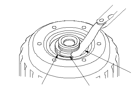
| 39. | Install the 25.5 mm cotters to the cotter groove on the driven pulley shaft, then measure the clearance between the cotters (A) and the start clutch guide (B) with a feeler gauge (C). Take measurements in at least three places, and use the average as the actual clearance.
| Standard: | 0-0.13 mm (0-0.005 in.) |
 BAC BAC |
| 40. | If the clearance is out of standard, remove the cotters, and measure its thickness.
|
| 41. | Select and install the new 25.5 mm cotters as a set, then recheck that the clearance is within the standard.
COTTERS, 25.5 mm| No. | Part Number | Thickness |
|---|
| A | 90429-P4V-000 | 2.9 mm (0.114 in.) | | B | 90430-P4V-000 | 3.0 mm (0.118 in.) | | C | 90431-P4V-000 | 3.1 mm (0.122 in.) | | D | 90432-P4V-000 | 3.2 mm (0.126 in.) |
|
| 42. | Install the cotter retainer and snap ring.
|
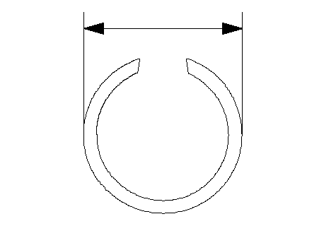
| 43. | Verify that the snap ring outside diameter (A) is 33.9 mm (1.33 in.) or less.
 A A |
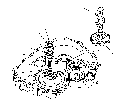
| 44. | Place the secondary driven gear (A) on the transmission housing with aligning to the secondary drive gear, then install the final drive shaft (B) through the secondary driven gear into the transmission housing.
 BAHFEDCG BAHFEDCG |
| 45. | Install the thrust washer (C), thrust needle bearing (D), thrust washer (E), and 22 x 28 mm thrust shim (F) on the input shaft (G), and install the snap ring (H) to secure them.
|
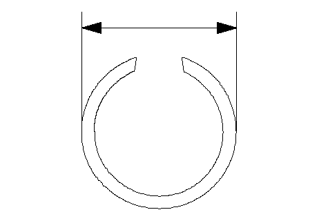
| 46. | Verify that the snap ring outside diameter (A) is 26.3 mm (1.04 in.) or less.
 A A |
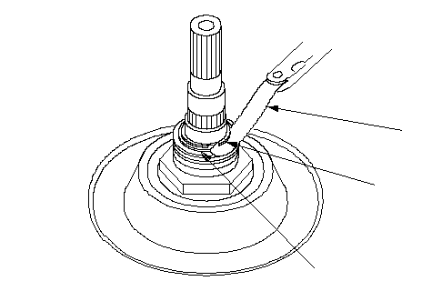
| 47. | Measure the clearance between the 22 x 28 mm thrust shim (A) and the snap ring (B) with a feeler gauge (C). Take measurements in at least three places, and use the average as the actual clearance.
| Standard: | 0.37-0.65 mm (0.015-0.026 in.) |
 CBA CBA |
| 48. | If the clearance is out of standard, remove the 22 x 28 mm thrust shim, and measure its thickness.
|
| 49. | Select and install the new 22 x 28 thrust shim, then recheck that the clearance is within the standard.
THRUST SHIM, 22 x 28 mm| No. | Part Number | Thickness |
|---|
| C | 90573-P4V-000 | 1.15 mm (0.045 in.) | | D | 90574-P4V-000 | 1.40 mm (0.055 in.) | | E | 90575-P4V-000 | 1.65 mm (0.065 in.) | | F | 90576-P4V-000 | 1.90 mm (0.075 in.) | | G | 90577-P4V-000 | 2.15 mm (0.085 in.) | | H | 90578-P4V-000 | 2.40 mm (0.095 in.) |
|
| 50. | If the 22 x 28 mm thrust shim is replaced, install the snap ring, and verify that the snap ring outside diameter is within the tolerance.
|
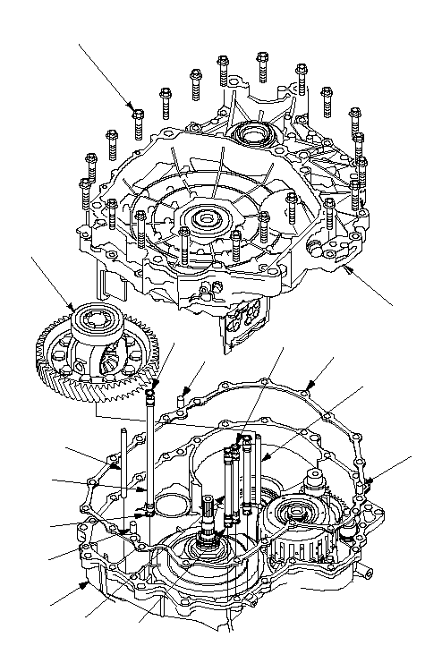
| 51. | Install the differential assembly (A).
 CBHEGEDBEFHEBAI8 x 1.25 mm CBHEGEDBEFHEBAI8 x 1.25 mm
29 N·m (3.0 kgf·m, 22 lbf·ft) |
| 52. | Install the dowel pins (3) (B) and the new gasket (C) on the transmission housing (D).
|
| 53. | Install the new O-ring (E) on the 11 x 230.5 mm ATF pipe (F) and 11 x 134.5 mm ATF pipes (G), then install them in the transmission housing. Install the 8 x 133.5 mm ATF pipe (H) in the transmission housing.
|
| 54. | Assemble the flywheel housing.
|
| 55. | Install the flywheel housing (I) on the transmission housing.
|
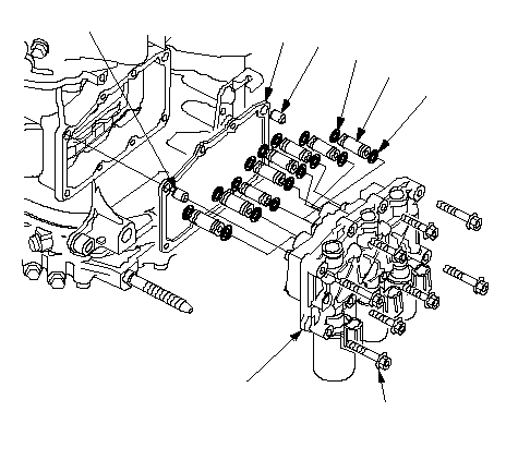
| 56. | Install the dowel pins (2) (A) and the new gasket (B) on the transmission housing.
 ABADCE6 × 1.0 mm ABADCE6 × 1.0 mm
12 N·m
(1.2 kgf·m, 8.7 lbf·ft)C |
| 57. | Install the new O-ring (C) on the ATF pipes (8) (D), then install them in the ATF pass body inside the transmission.
|
| 58. | Install the control valve body (E) on the transmission housing.
|
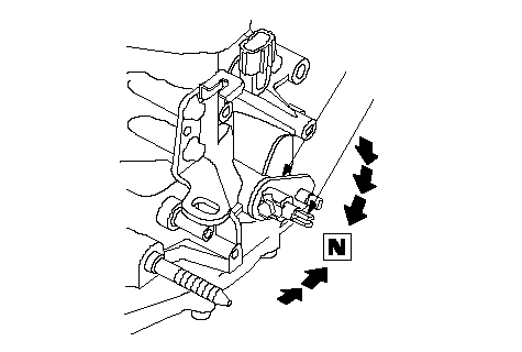
| 59. | Move the control lever (A) to N position. Do not squeeze the control shaft tips (B) together when shift to N position. If the tips are squeezed together will cause a faulty signal or position due to the play between the control shaft and the transmission range switch.
 AB AB |
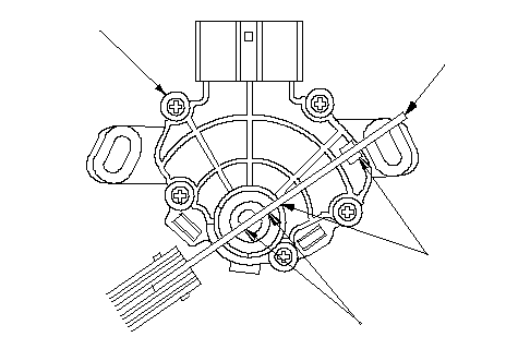
| 60. | Align the cutout (A) on the rotary-frame with the neutral positioning cutouts (B) on the transmission range switch (C), then put a 2.0 mm (0.08 in.) feeler gauge blade (D) in the cutouts to hold it in the N position. Be sure to use a 2.0 mm (0.08 in.) blade or equivalent to hold the switch in N position.
 ADCB ADCB |
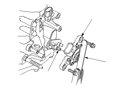
| 61. | Insert the transmission range switch (A) gently on the control shaft (B) with holding the N position with the 2.0 mm (0.08 in.) blade (C).
 CAB CAB |
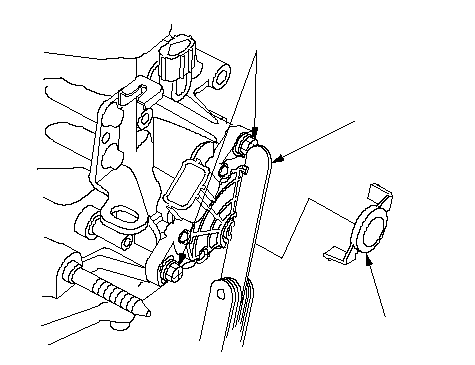
| 62. | Tighten the bolts on the transmission range switch while you continue to hold the N position. Do not move the transmission range switch when tightening the bolts.
 6 x 1.0 mm 6 x 1.0 mm
12 N·m (1.2 kgf·m, 8.7 lbf·ft)BA |
| 63. | Remove the feeler gauge (A), then install the rotary frame cover (B).
|
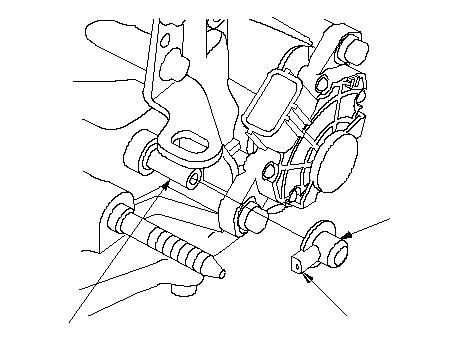
| 64. | Install the breather cap (A) with facing its vent (B) front side (opposite the transmission range switch) on the breather pipe (C).
 CBA CBA |
| 65. | Install the CVT drive pulley speed sensor, CVT driven pulley speed sensor, CVT speed sensor, inhibitor solenoid, ATF dipstick guide pipe with the new O-rings.
|
| 66. | Install the ATF cooler lines with joint bolts and the new sealing washers.
|