DTC Troubleshooting: 42, 45 (HATC Model)
DTC Troubleshooting: 42, 45
| DTC 42, 45: | Motor Driven Current |
| 1. | Clear the DTC. |
| 2. | Start the engine. |
| 3. | Turn the steering wheel from lock to lock several times, and wait 10 seconds or more. Does the EPS indicator come on? YES - Go to 4. NO - The system is OK at this time.n |
| 4. | Stop the engine, and verify the DTC. Is DTC 42 or 45 indicated? YES - Go to 5. NO - Perform the appropriate troubleshooting for the code indicated.n |
| 5. | Make sure the ignition switch is OFF. |
| 6. | Disconnect the negative cable from the battery. |
| 7. | Disconnect the EPS control unit A connector (4P), motor relay 4P connector and motor 2P connector. |
| 8. | Check for continuity between the EPS control unit connector A (4P) terminal No. 1 and body ground.
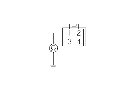 EPS CONTROL UNIT CONNECTOR A (4P)Wire side of female terminalsM+ (RED) EPS CONTROL UNIT CONNECTOR A (4P)Wire side of female terminalsM+ (RED)Is there continuity? YES - Repair short to body ground in the RED wire between the EPS control unit and motor relay.n NO - Go to 9. |
| 9. | Check for continuity between the motor relay 4P connector terminal No. 1 and body ground.
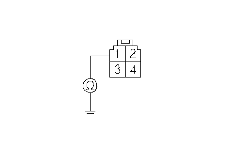 MOTOR RELAY 4P CONNECTORWire side of female terminalsWHT/RED MOTOR RELAY 4P CONNECTORWire side of female terminalsWHT/REDIs there continuity? YES - Repair short to body ground in the WHT/RED wire between the motor and motor relay.n NO - Go to 10. |
| 10. | Check for continuity between the EPS control unit connector A (4P) terminal No. 3 and body ground.
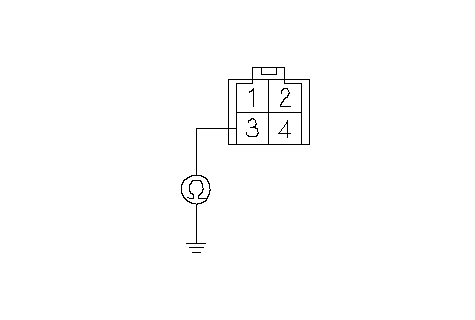 EPS CONTROL UNIT CONNECTOR A (4P)Wire side of female terminalsM- (GRN) EPS CONTROL UNIT CONNECTOR A (4P)Wire side of female terminalsM- (GRN)Is there continuity? YES - Repair short to body ground in the GRN wire between the EPS control unit and motor.n NO - Go to 11. |
| 11. | Check for continuity between the EPS control unit connector A (4P) terminal No. 1 and No. 3.
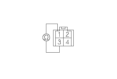 EPS CONTROL UNIT CONNECTOR A (4P)Wire side of female terminalsM+ (RED)M- (GRN) EPS CONTROL UNIT CONNECTOR A (4P)Wire side of female terminalsM+ (RED)M- (GRN)Is there continuity? YES - Repair short between the RED and GRN wires in the motor circuit between the EPS control unit and motor.n NO - Go to 12. |
| 12. | Check for continuity between the EPS control unit connector A (4P) terminal No. 3 and the motor relay 4P connector terminal No. 1.
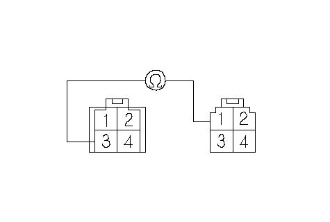 EPS CONTROL UNIT EPS CONTROL UNITCONNECTOR A (4P)Wire side of female terminalsM- (GRN)WHT/REDMOTOR RELAY 4P CONNECTOR Is there continuity? YES - Repair short between the GRN and WHT/RED wires in the motor circuit between the EPS control unit and motor.n NO - Go to 13. |
| 13. | Check for continuity between the EPS control unit connector A (4P) terminal No. 3 and the motor relay 4P connector terminal No. 4.
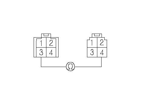 EPS CONTROL UNIT EPS CONTROL UNITCONNECTOR A (4P)Wire side of female terminalsM- (GRN)BLKMOTOR RELAY 4P CONNECTOR Is there continuity? YES - Repair short between the GRN and BLK wires in the motor circuit between the EPS control unit and motor.n NO - Go to 14. |
| 14. | Reconnect the negative cable to the battery. |
| 15. | Turn the ignition switch ON (II) and measure the voltage between the EPS control unit connector A (4P) terminal No. 1 and body ground.
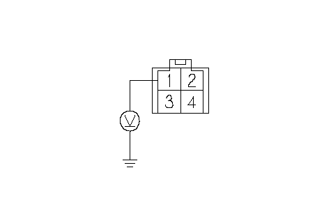 EPS CONTROL UNIT CONNECTOR A (4P)Wire side of female terminalsM+ (RED) EPS CONTROL UNIT CONNECTOR A (4P)Wire side of female terminalsM+ (RED)Is there battery voltage? YES - Repair short to power in the + circuit wire between the EPS control unit and motor relay.n NO - Go to 16. |
| 16. | Measure the voltage between the EPS control unit connector A (4P) terminal No. 3 and body ground.
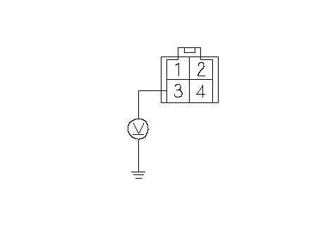 EPS CONTROL UNIT CONNECTOR A (4P)Wire side of female terminalsM- (GRN) EPS CONTROL UNIT CONNECTOR A (4P)Wire side of female terminalsM- (GRN)Is there battery voltage? YES - Repair short to power in the + circuit wire between the EPS control unit and motor.n NO - Go to 17. |
| 17. | Measure the voltage between the motor relay 4P connector terminal No. 1 and body ground.
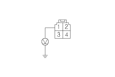 MOTOR RELAY 4P CONNECTORWire side of female terminalsWHT/RED MOTOR RELAY 4P CONNECTORWire side of female terminalsWHT/REDIs there battery voltage? YES - Repair short to power in the + circuit wire between the motor relay and motor.n NO - Go to 18. |
| 18. | Turn the ignition switch OFF and check for continuity between the EPS control unit connector A (4P) terminal No. 3 and the motor relay 4P connector terminal No. 3.
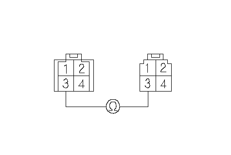 EPS CONTROL UNIT EPS CONTROL UNITCONNECTOR A (4P)Wire side of female terminalsM- (GRN)MOTOR RELAY 4P CONNECTORM- (GRN) Is there continuity? YES - Go to 19. NO - Repair open in the GRN wire between the EPS control unit and motor.n |
| 19. | Check for continuity between the motor relay 4P connector terminal No. 1 and the motor 2P connector terminal No. 1 (RHD: No. 2).
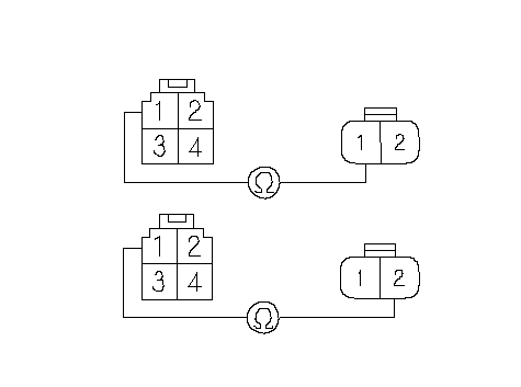 MOTOR RELAY 4P MOTOR RELAY 4PCONNECTORWire side of female terminalsMOTOR 2P CONNECTORLHD model:RHD model:WHT/REDWHT/REDWHT/REDWHT/RED Is there continuity? YES - Go to 20. NO - Repair open in the WHT/RED wire between the EPS control unit and motor.n |
| 20. | Check for continuity between the EPS control unit connector A (4P) terminal No. 1 and the motor 2P connector terminal No. 2 (RHD: No. 1).
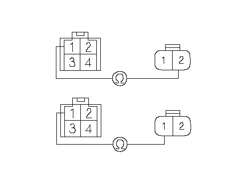 M+ (RED)EPS CONTROL UNIT M+ (RED)EPS CONTROL UNITCONNECTOR A (4P)Wire side of female terminalsMOTOR 2P CONNECTORLHD model:RHD model:M+ (RED)M+ (RED)M+ (RED) Is there continuity? YES - Go to 21. NO - Repair open in the RED wire between the EPS control unit and motor.n |
| 21. | Disconnect the negative cable from the battery. |
| 22. | Substitute a known-good EPS control unit, and connect the all disconnected connectors. |
| 23. | Reconnect the negative cable to the battery. |
| 24. | Start the engine. Does the EPS indicator come on? YES - Go to 25. NO - Check for loose EPS control unit connectors. If necessary, substitute a known-good EPS control unit and retest.n |
| 25. | Stop the engine, and verify the DTC. Is DTC 42 or 45 indicated? YES - Check for loose EPS control unit connectors, motor connector and power relay connector. If necessary, substitute a known-good steering gearbox and recheck.n NO - Perform the appropriate troubleshooting for the code indicated.n |