ABS Indicator Circuit Troubleshooting (With VSA)
ABS Indicator Circuit Troubleshooting
ABS indicator does not come on
| 1. | Do the gauge assembly self-diagnosis function. Is gauge assembly OK? YES - Go to 2. NO - Replace gauge assembly.n |
| 2. | Turn the ignition switch OFF. |
| 3. | Remove the gauge assembly. |
| 4. | Disconnect the gauge assembly connector C (40P). |
| 5. | Check for continuity between gauge assembly connector C (40P) terminal No. 26 and the body ground.
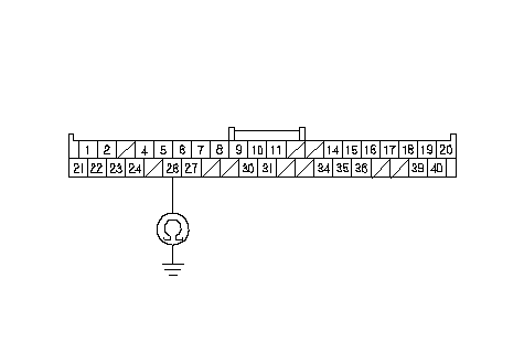 GAUGE ASSEMBLY CONNECTOR C (40P)Wire side of female terminalsWALP (BLU/RED) GAUGE ASSEMBLY CONNECTOR C (40P)Wire side of female terminalsWALP (BLU/RED)Is there continuity? YES - Repair short to body ground in the wire between the gauge assembly and the VSA modulator-control unit.n NO - Check for loose or poor connections in the gauge assembly connectors. If connections are good, replace the gauge assembly.n |
ABS indicator does not go off, and no DTCs are stored
| 1. | Check the No. 25 (7.5 A) fuse in the under-dash fuse/relay box. Is the fuse OK? YES - Go to 2. NO - Replace the fuse, and recheck. If the fuse is blown, check for a short to body ground in this fuse circuit. If the circuit is OK, replace the VSA modulator-control unit.n |
| 2. | Disconnect the VSA control unit 46P connector. |
| 3. | Turn the ignition switch ON (II). |
| 4. | Mesure the voltage between the VSA control unit 46P connector terminal No. 40 and body ground.
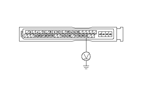 VSA CONTROL UNIT 46P CONNECTORWire side of female terminalsIG1 (YEL) VSA CONTROL UNIT 46P CONNECTORWire side of female terminalsIG1 (YEL)Is there battery voltage? YES - Go to 5. NO - Repair open in the wire between the No. 25 (7.5 A) fuse in the under-dash fuse/relay box and the VSA modulator-control unit.n |
| 5. | Turn the ignition switch OFF. |
| 6. | Check for continuity between the VSA control unit 46P connector terminal No. 43 and body ground.
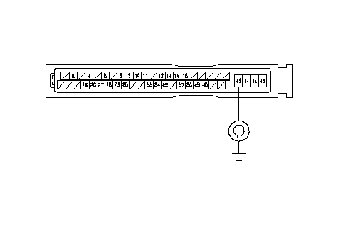 VSA CONTROL UNIT 46P CONNECTORWire side of female terminalsGND2 (BLK) VSA CONTROL UNIT 46P CONNECTORWire side of female terminalsGND2 (BLK)Is there continuity? YES - Go to 7. NO - Repir open in the wire between the VSA modulator-control unit and body ground (G202).n |
| 7. | Turn the ignition switch ON (II). |
| 8. | Connect the VSA control unit 46P connector terminal No. 4 and body ground with a jumper wire.
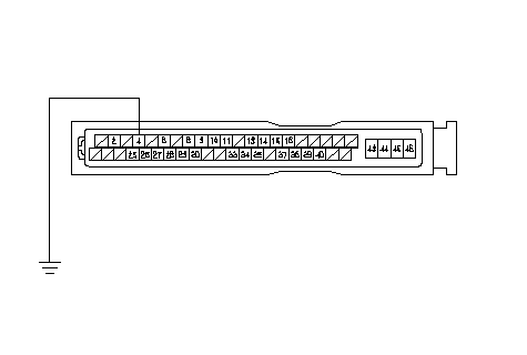 VSA CONTROL UNIT 46P CONNECTORWire side of female terminalsWALP (BLU/RED)JUMPER WIRE VSA CONTROL UNIT 46P CONNECTORWire side of female terminalsWALP (BLU/RED)JUMPER WIREDoes the ABS indicator go off? YES - Check for the loose or poor connections in the VSA control unit 46P connector. If necessary, substitute a known-good VSA modulator-control unit, and recheck.n NO - Go to 9. |
| 9. | Remove the gauge assembly, and leave the connectors connected. |
| 10. | Connect the gauge assembly connector C (40P) terminal No. 26 and body ground with a jumper wire.
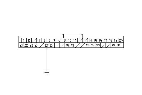 GAUGE ASSEMBLY CONNECTOR C (40P)Wire side of female terminalsWALP (BLU/RED)JUMPER WIRE GAUGE ASSEMBLY CONNECTOR C (40P)Wire side of female terminalsWALP (BLU/RED)JUMPER WIREDoes the ABS indicator go off? YES - Repair open in the wire between the gauge assembly and the VSA modulator-control unit.n NO - Check for loose or poor connections in the gauge assembly connectors. If connections are good, replace the gauge assembly.n |