DTC No.
| DTC Detection Condition
| Trouble Area
|
U0122
| - When the power switch is on (IG), a communication error between the brake booster with master cylinder (skid control ECU) and the driving support ECU is detected for approx. 3 seconds.
- When the power switch is on (IG), a communication error between the skid control ECU assembly and the seat belt control ECU is detected for approx. 3 seconds.
| - Brake booster with master cylinder (skid control ECU)
- CAN communication system
- Driving support ECU
- Wire harness or connector
|
U0123
| When the power switch is on (IG), a communication error between the yaw rate sensor and the driving support ECU is detected for approx. 1 second.
| - Yaw rate sensor
- CAN communication system
- Driving support ECU
|
U0126
| When the power switch is on (IG), a communication error between the steering angle sensor and the driving support ECU is detected for approx. 1 second.
| - Steering angle sensor
- CAN communication system
- Driving support ECU
|
U0140
| When the power switch is on (IG), communication stop between the main body ECU and seat belt control ECU continues for 6 seconds or more.
| - Main body ECU
- CAN communication system
- Seat belt control ECU
- Wire harness or connector
|
U0151
| When the power switch is on (IG), communication stop between the center airbag sensor and seat belt control ECU continues for 6 seconds or more.
| - Center airbag sensor
- CAN communication system
- Seat belt control ECU
- Wire harness or connector
|
U0293
| - When the power switch is on (IG), a communication error between the power management control ECU and brake booster with master cylinder (skid control ECU) is detected for approx. 1 second.
- When the power switch is on (IG), a communication error between the power management control ECU and driving support ECU is detected for approx. 1 second.
| - Power management control ECU
- Brake booster with master cylinder (skid control ECU)
- CAN communication system
- Driving support ECU
|
U1100
| When the power switch is on (IG), a communication error between the seat belt control ECU and the driving support ECU is detected for approx. 1 second.
| - Seat belt control ECU
- CAN communication system
- Driving support ECU
|
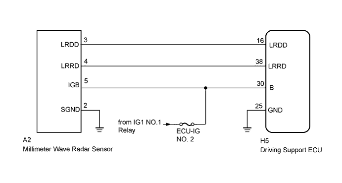
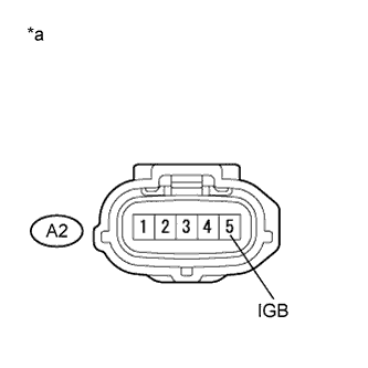
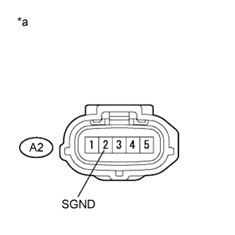
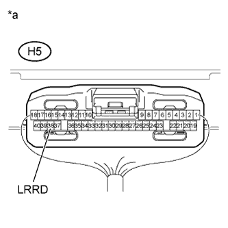
U1104
| - When the power switch is on (IG), a communication error between the driving support ECU and the millimeter wave radar sensor is detected for approx. 1 second.
- When the power switch is on (IG), a communication error between the driving support ECU and the power management control ECU is detected for approx. 1 second.
- When the power switch is on (IG), a communication error between the driving support ECU and seat belt control ECU is detected for approx. 1 second.
| - Communication circuit
- Millimeter wave radar sensor
- Driving support ECU
- CAN communication system
- Wire harness or connector
|