DTC    C1234/34    Yaw Rate Sensor Malfunction

DTC    C1243/43    Acceleration Sensor Stuck Malfunction

DTC    C1244/44    Open or Short in Acceleration Sensor Circuit

DTC    C1245/45    Acceleration Sensor Output Malfunction

DTC    C1279/79    Acceleration Sensor Output Voltage Malfunction (Test Mode DTC)

DTC    C1381/97    Acceleration Sensor Power Supply Voltage Malfunction

for Preparation Click here


DESCRIPTION

The skid control ECU receives signals from the yaw rate and acceleration sensor via the CAN communication system.
The yaw rate sensor has a built-in acceleration sensor and detects the vehicle's condition using 2 circuits (GL1, GL2).
If there are any problems in the bus lines between the yaw rate and acceleration sensor and the CAN communication system, DTCs U0123/62 (Lost Communication with Yaw Rate Sensor Module) and U0124/95 (Lost Communication with Lateral Acceleration Sensor Module) are output.
These DTCs are also output when calibration has not been completed.
DTC C1279/79 will be cleared when the yaw rate and acceleration sensor sends a yaw rate and/or acceleration signal or when Test Mode ends. DTC C1279/79 is output only in Test Mode.

DTC Code
INF Code
DTC Detection Condition
Trouble Area
C1234/34
711
While yaw rate sensor communication is enabled, a malfunction signal output is received during the sensor self-check (Sensor 1 (GL1) malfunction).
Yaw rate and acceleration sensor internal malfunction

712
While yaw rate sensor communication is enabled, a malfunction signal output is received during the sensor self-check (Sensor 2 (GL2) malfunction).


713
While yaw rate sensor communication is enabled, a malfunction signal output is received during the sensor self-check (Zero point calibration malfunction).


714
While yaw rate sensor communication is enabled, a malfunction signal output is received during the sensor self-check (Two-value comparison malfunction).

C1243/43
561
An acceleration sensor malfunction occurs 16 times or more when the vehicle speed drops from above 30 km/h (19 mph) to 0 km/h (0 mph).
Yaw rate and acceleration sensor internal stuck malfunction

562
563
564
A stuck acceleration sensor value is determined.

C1244/44
571
Either of the following is detected:
  1. Difference between GL1 and GL2 does not become less than 0.4 G for 60 seconds or more after reaching 0.6 G when the vehicle is stopped.
  2. A malfunction signal from the acceleration sensor is received.
  1. Yaw rate and acceleration sensor installed improperly
  2. Yaw rate and acceleration sensor
C1245/45
581
Difference between longitudinal G calculated from the acceleration sensor value and that calculated from the vehicle speed exceeds 0.35 G for 60 seconds or more.
  1. Yaw rate and acceleration sensor installed improperly
  2. Yaw rate and acceleration sensor
C1381/97
601
While yaw rate and acceleration sensor communication is enabled, a supply voltage malfunction signal is received from the sensor for 10 seconds.
  1. Yaw rate and acceleration sensor supply voltage shut down
  2. Yaw rate and acceleration sensor
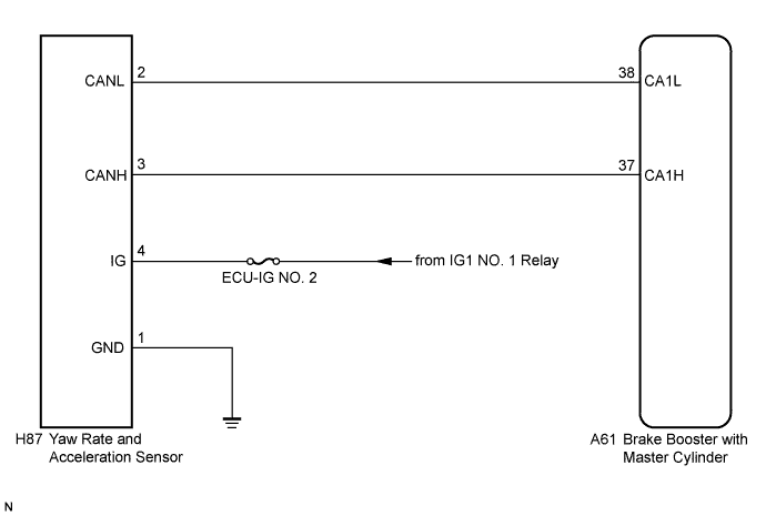
  3. Brake booster with master cylinder (Skid control ECU)
C1279/79
-
Detected only during Test Mode.
  1. Sensor installation
  2. Yaw rate and acceleration sensor

WIRING DIAGRAM


C167661E38


INSPECTION PROCEDURE

NOTICE:
When replacing the yaw rate and acceleration sensor, perform zero point calibration (Click here).

HINT:
When U0123/62 and/or U0124/95 is output together with C1234/34, C1243/43, C1244/44, C1245/45, and/or C1381/97, inspect and repair the trouble areas indicated by U0123/62 and/or U0124/95 first (Click here).

1.CHECK DTC
  1. Clear the DTCs (Click here).

  1. Turn the power switch off.

  1. Turn the power switch on (READY).

  1. Drive the vehicle at a speed of 30 km/h (19 mph) or more, turn the steering wheel, and decelerate (depress the brake pedal) the vehicle.

  1. Turn the power switch on (IG) again and check that no CAN communication system DTC is output (Click here).

  1. Check if DTC C1210/36 (Zero Point Calibration of Yaw Rate Sensor Undone) or C1336/98 (Zero Point Calibration of Acceleration Sensor Undone) is output (Click here).

    Result:

    Result
    Proceed to
    DTCs (C1210/36, C1336/98 and CAN communication system DTC) are not output
    A
    CAN communication system DTC is output
    B
    DTCs (C1210/36 and/or C1336/98) are output
    C


B
INSPECT CAN COMMUNICATION SYSTEM (Click here)

C
REPAIR CIRCUITS INDICATED BY OUTPUT DTCS (Click here)
A


2.CHECK YAW RATE AND ACCELERATION SENSOR INSTALLATION
  1. Turn the power switch off.

  1. Check that the yaw rate and acceleration sensor has been installed properly (Click here).

    OK:
    The sensor is tightened to the specified torque.
    The sensor is not tilted.


NG
INSTALL YAW RATE AND ACCELERATION SENSOR CORRECTLY (Click here)
OK


3.INSPECT YAW RATE AND ACCELERATION SENSOR (IG TERMINAL)


    C235291E01
  1. Make sure that there is no looseness at the locking part and the connecting part of the connector.

  1. Disconnect the yaw rate and acceleration sensor connector.

  1. Turn the power switch on (IG).

  1. Measure the voltage according to the value(s) in the table below.

    Standard Voltage:
    Tester Connection
    Switch Condition
    Specified Condition
    H87-4 (IG) - Body ground
    Power switch on (IG)
    11 to 14 V

    Text in Illustration 
    *a
    Front view of wire harness connector
    (to Yaw Rate and Acceleration Sensor)


NG
REPAIR OR REPLACE HARNESS OR CONNECTOR (IG CIRCUIT)
OK


4.INSPECT YAW RATE AND ACCELERATION SENSOR (GND TERMINAL)


    C235291E02
  1. Turn the power switch off.

  1. Measure the resistance according to the value(s) in the table below.

    Standard Resistance:
    Tester Connection
    Condition
    Specified Condition
    H87-1 (GND) - Body ground
    Always
    Below 1 Ω

    Text in Illustration 
    *a
    Front view of wire harness connector
    (to Yaw Rate and Acceleration Sensor)

    NOTICE:
    Check the yaw rate and acceleration sensor signal after replacement (Click here).

    HINT:
    If troubleshooting has been carried out according to Problem Symptoms Table, refer back to the table and proceed to the next step (Click here).


NG
REPAIR OR REPLACE HARNESS OR CONNECTOR (GND CIRCUIT)
OK

REPLACE YAW RATE AND ACCELERATION SENSOR (Click here)