FRONT SHOCK ABSORBER > INSTALLATION |
| 1. SECURE FRONT SHOCK ABSORBER ASSEMBLY |
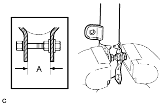 |
Install a bolt and nut to the front shock absorber as shown in the illustration and secure the front shock absorber in a vise.
| 2. INSTALL FRONT LOWER COIL SPRING INSULATOR |
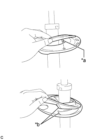 |
Install the front lower coil spring insulator to the front shock absorber assembly.
| *a | Positioning Pin |
| *b | Depression |
| 3. INSTALL FRONT SPRING BUMPER |
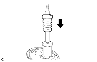 |
Install the front spring bumper to the front shock absorber assembly.
| 4. INSTALL FRONT COIL SPRING |
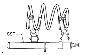 |
Using SST, compress the front coil spring.
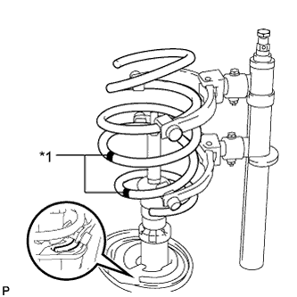 |
Install the front coil spring.
| *1 | Paint Mark |
| 5. INSTALL FRONT UPPER COIL SPRING INSULATOR |
| 6. INSTALL FRONT UPPER COIL SPRING SEAT |
Install the front upper coil spring seat to the front shock absorber assembly.
| 7. INSTALL FRONT SUSPENSION SUPPORT DUST SEAL |
Install a new front suspension support dust seal.
| 8. INSTALL FRONT SUSPENSION SUPPORT SUB-ASSEMBLY |
Install the front suspension support sub-assembly to the front shock absorber assembly.
| 9. TEMPORARILY TIGHTEN FRONT SUPPORT TO FRONT SHOCK ABSORBER NUT |
Temporarily tighten a new front support to front shock absorber nut.
Remove SST from the front coil spring.
| 10. INSTALL FRONT SHOCK ABSORBER WITH COIL SPRING |
Install the front shock absorber with coil spring (upper side) with the 3 nuts.
Install the front shock absorber with coil spring (lower side) to the steering knuckle with the 2 bolts and 2 nuts.
| 11. FULLY TIGHTEN FRONT SUPPORT TO FRONT SHOCK ABSORBER NUT |
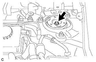 |
Fully tighten the front support to front shock absorber nut.
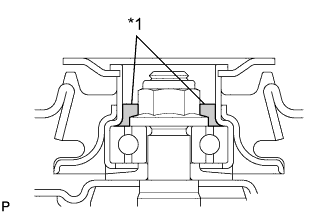 |
Apply MP grease into the suspension support sub-assembly.
| *1 | MP Grease |
| 12. INSTALL FRONT SUSPENSION SUPPORT DUST COVER |
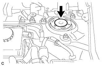 |
Install the front suspension support dust cover.
| 13. INSTALL FRONT SPEED SENSOR |
Install the front speed sensor and front flexible hose to the front shock absorber with coil spring with the bolt and clamp.
| 14. INSTALL FRONT STABILIZER LINK ASSEMBLY |
Install the front stabilizer link assembly to the front shock absorber with coil spring with the nut.
| 15. INSTALL OUTER COWL TOP PANEL SUB-ASSEMBLY (for LHD) |
Install the outer cowl top panel sub-assembly with the 9 bolts.
w/ Wiper Deicer:
Engage the 3 clamps to install the wire harness.
Engage the clamp to install the wire harness.
| 16. INSTALL OUTER COWL TOP PANEL SUB-ASSEMBLY (for RHD) |
Install the outer cowl top panel sub-assembly with the 9 bolts.
w/ Wiper Deicer:
Engage the 3 clamps to install the wire harness.
Engage the clamp to install the wire harness.
| 17. INSTALL COWL BODY MOUNTING REINFORCEMENT LH (for LHD) |
Install the cowl body mounting reinforcement LH with the 2 bolts.
| 18. INSTALL COWL BODY MOUNTING REINFORCEMENT RH (for RHD) |
Install the cowl body mounting reinforcement RH with the 2 bolts.
| 19. INSTALL NO. 2 HEATER AIR DUCT SPLASH SHIELD SEAL (for LHD) |
Engage the claw and guide to install the No. 2 heater air duct splash shield seal.
| 20. INSTALL NO. 2 HEATER AIR DUCT SPLASH SHIELD SEAL (for RHD) |
Engage the claw and guide to install the No. 2 heater air duct splash shield seal.
| 21. INSTALL NO. 1 HEATER AIR DUCT SPLASH SHIELD SEAL (for LHD) |
Engage the 2 claws to install the No. 1 heater air duct splash shield seal.
| 22. INSTALL NO. 1 HEATER AIR DUCT SPLASH SHIELD SEAL (for RHD) |
Engage the 2 claws to install the No. 1 heater air duct splash shield seal.
| 23. INSTALL WINDSHIELD WIPER MOTOR AND LINK ASSEMBLY |
| 24. INSTALL FRONT WHEEL |
| 25. INSPECT AND ADJUST FRONT WHEEL ALIGNMENT |
