FRONT SUSPENSION MEMBER > REMOVAL |
| 1. PLACE FRONT WHEELS FACING STRAIGHT AHEAD |
| 2. SECURE STEERING WHEEL |
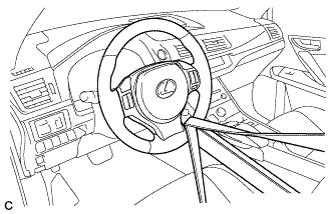 |
Secure the steering wheel with the seat belt in order to prevent rotation.
| 3. REMOVE COLUMN HOLE COVER SILENCER SHEET |
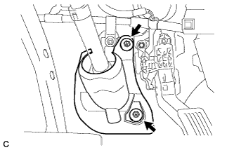 |
Turn back the floor carpet.
Remove the 2 clips and column hole cover silencer sheet.
| 4. SEPARATE NO. 2 STEERING INTERMEDIATE SHAFT ASSEMBLY |
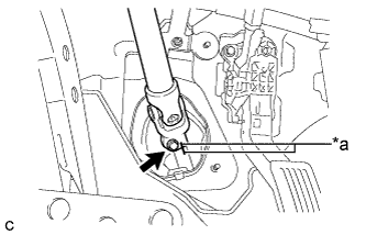 |
Put matchmarks on the No. 2 steering intermediate shaft assembly and steering intermediate shaft.
| *a | Matchmark |
Remove the bolt.
Separate the No. 2 steering intermediate shaft assembly from the steering intermediate shaft.
| 5. SEPARATE NO. 1 STEERING COLUMN HOLE COVER SUB-ASSEMBLY |
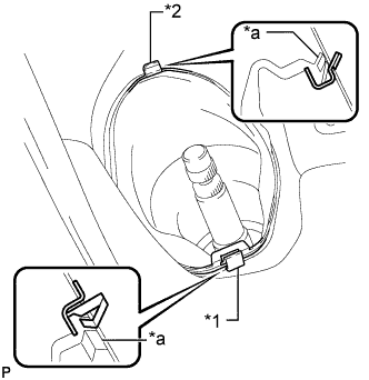 |
Remove clip A, detach clip B from the body and disconnect the No. 1 steering column hole cover sub-assembly.
| *1 | Clip A |
| *2 | Clip B |
| *a | Lip |
| 6. REMOVE FRONT WHEELS |
| 7. REMOVE NO. 1 ENGINE UNDER COVER |
| 8. REMOVE FRONT NO. 3 ENGINE UNDER COVER |
| 9. REMOVE REAR ENGINE UNDER COVER LH |
| 10. REMOVE REAR ENGINE UNDER COVER RH |
| 11. REMOVE FRONT LOWER BUMPER ABSORBER |
| 12. SEPARATE FRONT STABILIZER LINK ASSEMBLY LH |
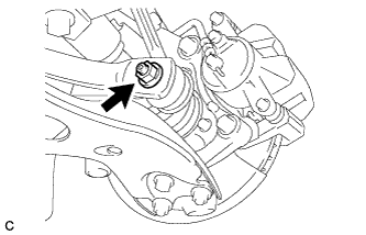 |
Remove the nut and separate the front stabilizer link assembly LH from the front stabilizer bar.
| 13. SEPARATE FRONT STABILIZER LINK ASSEMBLY RH |
| 14. SEPARATE TIE ROD END SUB-ASSEMBLY LH |
Remove the clip and nut.
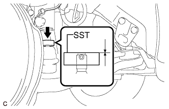 |
Install SST to the tie rod end.
Secure SST using a string.
Using SST, separate the tie rod end from the steering knuckle.
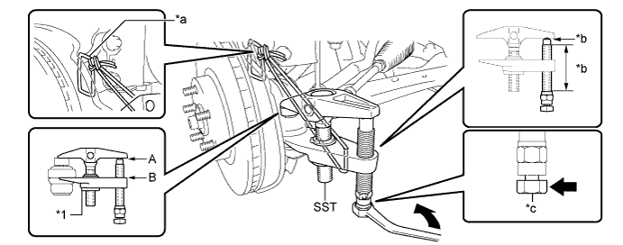
| *1 | Center Nut | - | - |
| *a | String | *b | Grease Application Area |
| *c | Place the wrench here. | - | - |
| 15. SEPARATE TIE ROD END SUB-ASSEMBLY RH |
| 16. SEPARATE FRONT LOWER NO. 1 SUSPENSION ARM SUB-ASSEMBLY LH |
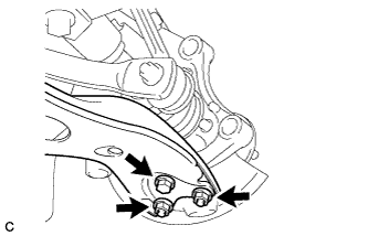 |
Remove the bolt and 2 nuts, and separate the front lower No. 1 suspension arm sub-assembly from the front lower ball joint assembly.
| 17. SEPARATE FRONT LOWER NO. 1 SUSPENSION ARM SUB-ASSEMBLY RH |
| 18. REMOVE FRONT ENGINE MOUNTING BRACKET LOWER REINFORCEMENT |
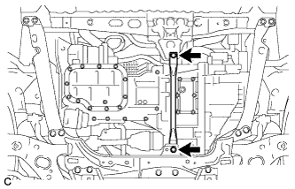 |
Remove the 2 bolts and front engine mounting bracket lower reinforcement.
| 19. REMOVE REAR SIDE RAIL REINFORCEMENT SUB-ASSEMBLY LH |
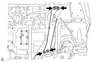 |
Remove the 4 bolts and rear side rail reinforcement sub-assembly LH.
| 20. REMOVE REAR SIDE RAIL REINFORCEMENT SUB-ASSEMBLY RH |
| 21. REMOVE FRONT SUSPENSION MEMBER REAR BRACE LH |
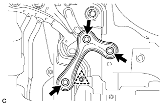 |
Remove the 3 bolts, clip and front suspension member rear brace LH.
| 22. REMOVE FRONT SUSPENSION MEMBER REAR BRACE RH |
| 23. REMOVE FRONT SUSPENSION CROSSMEMBER SUB-ASSEMBLY |
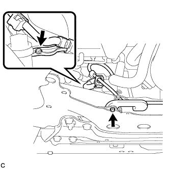 |
Remove the 2 bolts and 2 wiring harness clamp brackets from the front suspension crossmember sub-assembly.
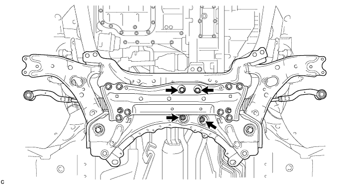
Remove the 2 bolts and 2 nuts, and separate the front suspension crossmember sub-assembly from the rear engine mounting insulator.
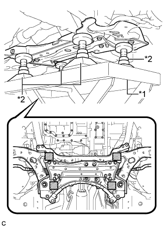 |
Support the front suspension crossmember sub-assembly with an engine lifter using 4 attachments or equivalent tools as shown in the illustration.
| *1 | Engine Lifter |
| *2 | Attachment |
 | Attachment placement location |
Remove the 2 bolts and front suspension crossmember sub-assembly.
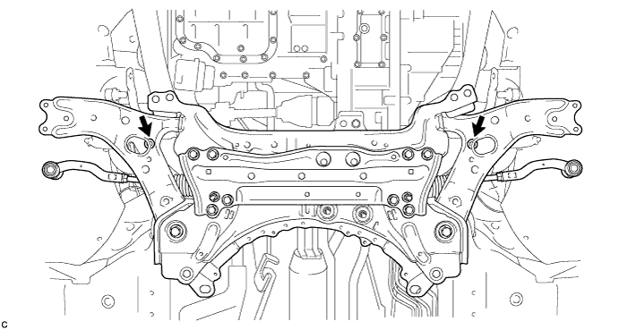
Slowly lower the front suspension crossmember sub-assembly.
| 24. REMOVE FRONT CROSS MEMBER SUB-ASSEMBLY |
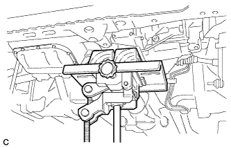 |
Using a jack, support the engine and transaxle assembly.
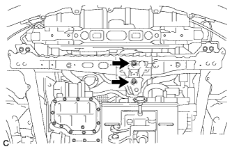 |
Remove the 2 bolts and separate the front cross member sub-assembly from the front engine mounting insulator.
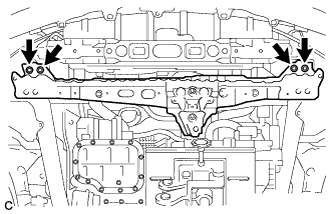 |
Remove the 4 bolts and front cross member sub-assembly.
| 25. REMOVE STEERING LINK ASSEMBLY |
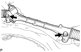 |
Remove the 2 bolts, 2 nuts and steering link assembly from the front suspension crossmember sub-assembly.
| 26. REMOVE FRONT LOWER NO. 1 SUSPENSION ARM SUB-ASSEMBLY LH |
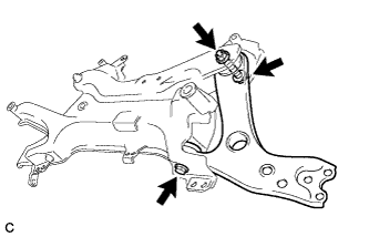 |
Remove the 2 bolts, nut and front lower No. 1 suspension arm sub-assembly LH from the front suspension crossmember sub-assembly.
| 27. REMOVE FRONT LOWER NO. 1 SUSPENSION ARM SUB-ASSEMBLY RH |
| 28. REMOVE FRONT SUSPENSION MEMBER BRACE |
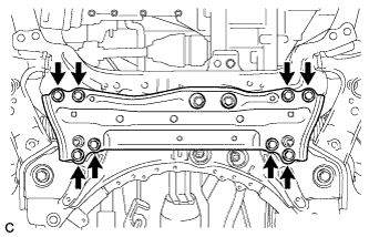 |
Remove the 8 bolts and front suspension member brace from the front suspension crossmember sub-assembly.
| 29. REMOVE FRONT STABILIZER BAR |
Remove the front stabilizer bar with front stabilizer bar bushings from the front suspension crossmember sub-assembly.
