FRONT STABILIZER BAR > INSTALLATION |
| 1. INSTALL FRONT STABILIZER BAR BUSHING LH |
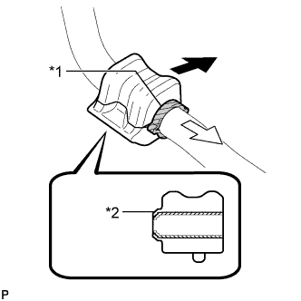 |
Install the front stabilizer bar bushing to the outside of the stopper on the front stabilizer bar as shown in the illustration.
| *1 | Stopper |
| *2 | Dust Lip |
 | Front of the Vehicle |
 | Inside of the Vehicle |
| 2. INSTALL FRONT STABILIZER BAR BUSHING RH |
| 3. INSTALL FRONT STABILIZER BAR |
Install the front stabilizer bar to the front suspension crossmember sub-assembly so that the identification marks are positioned on the right side of the vehicle.
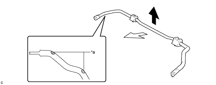
| *a | Identification Mark | - | - |
| Top of the Vehicle | | Front of the Vehicle |
| 4. INSTALL FRONT SUSPENSION MEMBER BRACE |
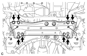 |
Install the front suspension member brace with the 8 bolts.
| *a | Protrusion |
| 5. TEMPORARILY INSTALL FRONT LOWER NO. 1 SUSPENSION ARM SUB-ASSEMBLY LH |
Temporarily install the front lower No. 1 suspension arm sub-assembly LH to the front suspension crossmember sub-assembly with the 2 bolts and nut.
| 6. CONNECT FRONT LOWER NO. 1 SUSPENSION ARM SUB-ASSEMBLY LH |
Install the front lower No. 1 suspension arm sub-assembly to the front lower ball joint assembly with the bolt and 2 nuts.
| 7. INSTALL FRONT STABILIZER LINK ASSEMBLY LH |
Install the front stabilizer link assembly LH with the 2 nuts.
| 8. INSTALL FRONT STABILIZER LINK ASSEMBLY RH |
| 9. INSTALL FRONT WHEELS |
| 10. STABILIZE SUSPENSION |
Lower the vehicle.
Press down on the vehicle several times to stabilize the suspension.
| 11. FULLY TIGHTEN FRONT LOWER NO. 1 SUSPENSION ARM SUB-ASSEMBLY LH |
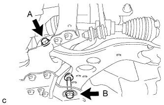 |
Fully tighten the bolt A and B.
| 12. INSTALL NO. 1 ENGINE UNDER COVER |
| 13. INSPECT AND ADJUST FRONT WHEEL ALIGNMENT |
