RADIATOR > INSTALLATION |
| 1. INSTALL RADIATOR ASSEMBLY |
Install the radiator assembly with the 2 bolts.
Install the 2 lower radiator supports.
Install the radiator assembly with the fan shroud.
Connect the 2 connectors and 2 clamps.
| 2. INSTALL NO. 2 FAN SHROUD |
Install the No. 2 fan shroud with the 2 bolts and 2 claws.
| 3. CONNECT NO. 3 WATER BY-PASS HOSE |
Connect the No. 3 water by-pass hose and 4 clamps.
| 4. CONNECT NO. 1 WATER BY-PASS HOSE |
Connect the No. 1 water by-pass hose.
| 5. CONNECT NO. 5 INVERTER COOLING HOSE |
Connect the 3 clamps and No. 5 inverter cooling hose to the fan shroud.
| 6. CONNECT NO. 1 RADIATOR HOSE |
Connect the No. 1 radiator hose.
| 7. CONNECT NO. 2 RADIATOR HOSE |
Connect the No. 2 radiator hose.
| 8. INSTALL RADIATOR SUPPORT CUSHION |
Install the 2 radiator support cushions.
| 9. INSTALL HOOD LOCK SUPPORT SUB-ASSEMBLY |
Install the hood lock support sub-assembly with the 4 bolts.
Install the No. 2 water by-pass hose to the hood lock support sub-assembly with the bolt.
| 10. INSTALL NO. 1 INVERTER BRACKET |
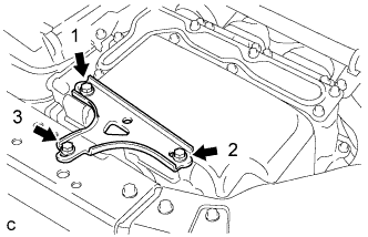 |
Temporarily install the No. 1 inverter bracket with the 3 bolts.
Tighten the 3 bolts in the order shown in the illustration.
| 11. INSTALL COOL AIR INTAKE DUCT RETAINER SUB-ASSEMBLY |
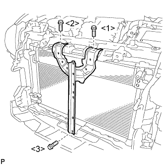 |
Install the cool air intake duct retainer sub-assembly with the 3 bolts.
| 12. INSTALL HOOD LOCK ASSEMBLY (w/o Engine Hood Courtesy Switch) |
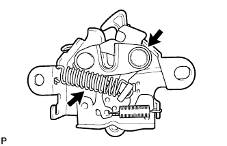 |
Apply MP grease to the sliding areas of the lock.
Connect the hood lock control cable.
Install the hood lock assembly with the 2 bolts and hood lock bolt.
Install a new hood lock nut cap.
| 13. INSTALL HOOD LOCK ASSEMBLY (w/ Engine Hood Courtesy Switch) |
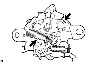 |
Apply MP grease to the sliding areas of the lock.
Connect the hood lock control cable.
Install the hood lock assembly with the 2 bolts and hood lock bolt.
Install a new hood lock nut cap.
Engage the clamp.
Connect the connector.
| 14. INSTALL MILLIMETER WAVE RADAR SENSOR ASSEMBLY (w/ Dynamic Radar Cruise Control System) |
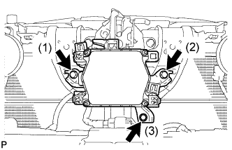 |
Tighten the 3 bolts on the millimeter wave radar sensor assembly.
Connect the connector.
| 15. INSTALL HIGH PITCHED HORN ASSEMBLY |
Install the high pitched horn assembly with the bolt.
Connect the connector.
| 16. INSTALL LOW PITCHED HORN ASSEMBLY |
Install the low pitched horn assembly with the bolt.
Connect the connector.
| 17. INSTALL FRONT BUMPER ASSEMBLY |
| 18. INSTALL AIR CLEANER CASE |
Install the air cleaner case with the 2 bolts.
Install the water hose to the hose clamp.
Install the air cleaner filter element sub-assembly.
| 19. INSTALL INLET AIR CLEANER ASSEMBLY |
Install the inlet air cleaner assembly to the air cleaner case.
Install the inlet air cleaner assembly with the 2 bolts and 2 clips.
Connect the wire harness clamp to the inlet air cleaner assembly.
Install the water hose to the hose clamp.
| 20. INSTALL AIR CLEANER CAP SUB-ASSEMBLY |
Install the air cleaner cap sub-assembly with the 2 clamps.
Tighten the hose clamp.
Connect the mass air flow meter connector.
Connect the wire harness clamp.
| 21. CONNECT CABLE TO NEGATIVE BATTERY TERMINAL |
| 22. ADD COOLANT (for Engine) |
Tighten the radiator drain cock plug.
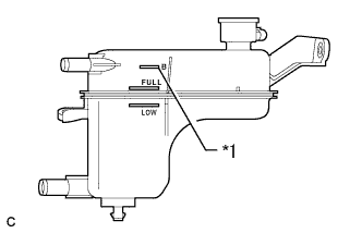 |
Add coolant to B line of the reserve tank.
| *1 | B Line |
| Item | Capacity |
| Engine coolant | w/ Exhaust Heat Recirculation System: 6.9 liters (7.3 US qts, 6.1 lmp. qts) |
| w/o Exhaust Heat Recirculation System: 6.5 liters (6.9 US qts, 5.7 lmp. qts) |
Squeeze the radiator hoses several times by hand, and then check the level of the coolant.
If the coolant level is low, add coolant.
Put the engine in inspection mode (Click here).
Install the reserve tank cap.
Bleed air from the cooling system.
Warm up the engine until the thermostat opens. While the thermostat is open, allow the coolant to circulate for several minutes. (●1)
Stop the engine and wait until the coolant cools down. Then if the coolant level is below the low line, add coolant so that the level will be between the full and low lines. (●2)
Repeat the steps from (●1) to (●2) until the coolant level of the reserve tank remains above the low line.
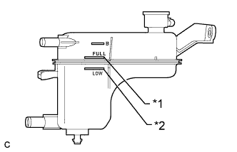 |
After the engine has cooled down, check that the coolant level is between the full and low lines.
| *1 | Full Line |
| *2 | Low Line |
| 23. INSPECT FOR COOLANT LEAK (for Engine) |
Remove the reserve tank cap.
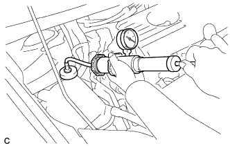 |
Fill the reserve tank with coolant, and then attach a radiator cap tester.
Put the engine in inspection mode (Click here).
Warm up the engine.
Using a radiator cap tester, increase the pressure inside the radiator to 108 kPa (1.1 kgf/cm2, 16 psi), and check that the pressure does not drop. If the pressure drops, check the hoses, radiator, front exhaust pipe assembly, the heater hose around the engine coolant temperature sensor and engine water pump assembly for leaks. If no external leaks are found, check the heater core, cylinder block and cylinder head.
Remove the radiator cap tester.
Install the reserve tank cap.
| 24. INSTALL NO. 1 ENGINE UNDER COVER |
| 25. INSTALL RADIATOR SUPPORT OPENING COVER |
Install the radiator support opening cover with the 9 clips.
| 26. INSTALL INVERTER COVER ASSEMBLY LH (w/ Cover) |
Engage the claw and install the inverter cover assembly LH.
Install the 2 clips.
| 27. INSTALL NO. 2 CYLINDER HEAD COVER |
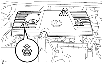 |
Engage the 3 clips to install the cover.
| 28. INSTALL REAR FLOOR BOARD UPPER NO. 3 PLATE |
Engage the 4 claws and 2 guides to install the rear floor board upper No. 3 plate.
| 29. INSTALL DECK FLOOR BOX RH |
Engage the 6 guides.
Install the deck floor box RH with the clip.
| 30. INSTALL REAR NO. 3 FLOOR BOARD |
Install the rear No. 3 floor board.
| 31. INSTALL REAR DECK FLOOR BOX |
Install the rear deck floor box.
| 32. INSTALL REAR NO. 2 FLOOR BOARD |
Install the rear No. 2 floor board.
| 33. ADJUST MILLIMETER WAVE RADAR SENSOR (w/ Dynamic Radar Cruise Control System) |
