WINDSHIELD GLASS > INSTALLATION |
| 1. INSTALL NO. 2 WINDSHIELD GLASS STOPPER (for 2-piece Type) |
Using a brush or sponge, coat the application area of 2 new No. 2 windshield glass stoppers with Primer G.
Install the 2 new No. 2 windshield glass stoppers onto the windshield glass, as shown in the illustration.
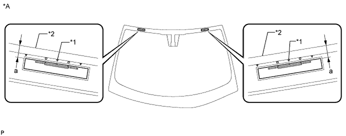
| *A | Back Side | - | - |
| *1 | Ceramic Notch | *2 | Windshield glass edge side |
| Area | Dimension |
| a | 13.7 to 14.7 mm (0.539 to 0.578 in.) |
| 2. INSTALL NO. 1 WINDSHIELD GLASS STOPPER (for 2-piece Type) |
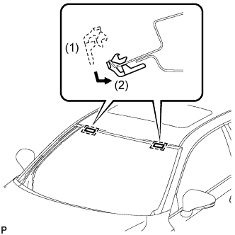 |
Install 2 new No. 1 windshield glass stoppers to the vehicle body as shown in the illustration.
| 3. INSTALL WINDSHIELD OUTSIDE MOULDING |
Using a brush or sponge, coat the application area of a new windshield outside moulding with Primer G.
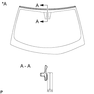 |
Install the windshield outside moulding onto the windshield glass as shown in the illustration.
| *A | Back Side |
| 4. INSTALL WINDSHIELD GLASS ADHESIVE DAM (for LHD) |
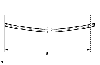 |
Cut the back window moulding lower so that it is the appropriate size as shown in the illustration.
| Area | Specified Condition |
| a | 2820 to 2830 mm (111.0 to 111.4 in.) |
Using a brush or sponge, coat the application area of a new windshield glass adhesive dam with Primer G.
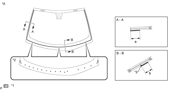
| *A | Back Side | - | - |
| *1 | Primer G | *2 | Ceramic Notch |
| Area | Dimension |
| a | 16.0 mm (0.630 in.) or more |
| b | 12.0 mm (0.472 in.) or more |
Install the windshield glass adhesive dam onto the windshield glass as shown in the illustration.
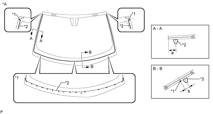
| *A | Back Side | - | - |
| *1 | Ceramic Notch | *2 | Windshield Glass Adhesive Dam |
| Area | Dimension |
| a | 9.5 mm (0.374 in.) |
| b | 6.5 mm (0.256 in.) |
| 5. INSTALL WINDSHIELD GLASS ADHESIVE DAM (for RHD) |
|
Cut the back window moulding lower so that it is the appropriate size as shown in the illustration.
| Area | Specified Condition |
| a | 2820 to 2830 mm (111.0 to 111.4 in.) |
Using a brush or sponge, coat the application area of a new windshield glass adhesive dam with Primer G.
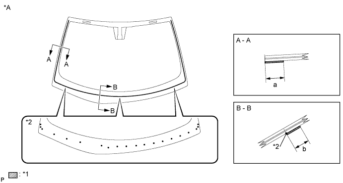
| *A | Back Side | - | - |
| *1 | Primer G | *2 | Ceramic Notch |
| Area | Dimension |
| a | 16.0 mm (0.630 in.) or more |
| b | 12.0 mm (0.472 in.) or more |
Install the windshield glass adhesive dam onto the windshield glass as shown in the illustration.
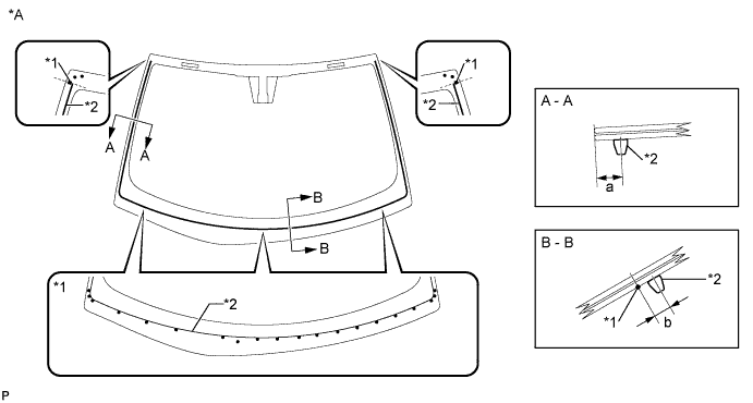
| *A | Back Side | - | - |
| *1 | Ceramic Notch | *2 | Windshield Glass Adhesive Dam |
| Area | Dimension |
| a | 9.5 mm (0.374 in.) |
| b | 6.5 mm (0.256 in.) |
| 6. INSTALL WINDSHIELD GLASS SUB-ASSEMBLY (for LHD) |
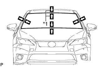 |
Position the windshield glass sub-assembly.
| *1 | Matchmark |
Using suction cups, place the windshield glass sub-assembly in the correct position.
Check that the whole contact surface of the windshield glass sub-assembly rim is perfectly even.
Align the matchmarks on the windshield glass sub-assembly and vehicle body.
Remove the windshield glass sub-assembly.
Using a brush, coat the installation surface on the vehicle body with Primer M.
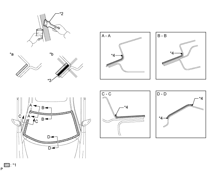
| *1 | Primer M | *2 | Brush |
| *3 | Adhesive | *4 | Edge of Curved Surface |
| *a | CORRECT | *b | WRONG |
Using a brush or sponge, coat the application area of adhesive with Primer G.
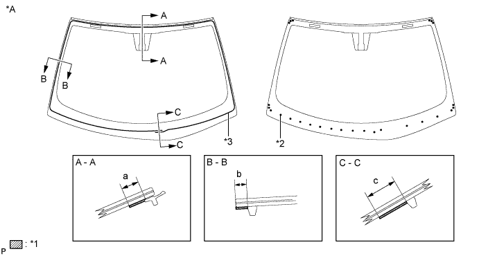
| *A | Back Side | - | - |
| *1 | Primer G | *2 | Ceramic Notch |
| *3 | Adhesive Center | - | - |
| Area | Dimension |
| a | 11.0 mm (0.433 in.) or more |
| b | 7.0 mm (0.276 in.) or more |
| c | 19.0 mm (0.748 in.) or more |
Apply adhesive to the glass.
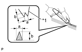 |
Cut off the tip of the cartridge nozzle as shown in the illustration.
| *1 | Nozzle |
| Area | Dimension |
| a | 8.0 mm (0.315 in.) or more |
| b | 12.0 mm (0.472 in.) or more |
| Temperature | Usage Time Frame |
| 35°C (95°F) | 15 minutes |
| 20°C (68°F) | 1 hour and 40 minutes |
| 5°C (41°F) | 8 hours |
Load the sealer gun with the cartridge.
Apply adhesive to the windshield glass sub-assembly as shown in the illustration.
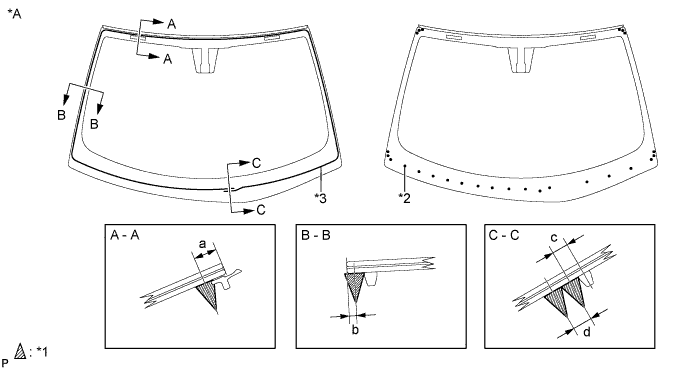
| *A | Back Side | - | - |
| *1 | Adhesive | *2 | Ceramic Notch |
| *3 | Adhesive Center | - | - |
| Area | Dimension |
| a | 9.4 to 10.7 mm (0.370 to 0.421 in.) |
| b | 3.0 mm (0.118 in.) |
| c | 6.5 mm (0.256 in.) |
| d | 8.0 mm (0.315 in.) |
|
Install the windshield glass sub-assembly.
| *1 | Matchmark |
Using suction cups, position the windshield glass so that the matchmarks are aligned, and press it in gently along the rim.
Lightly press the front surface of the windshield glass sub-assembly to ensure that the windshield glass is securely fit to the vehicle body.
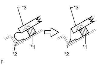 |
Using a scraper, remove any excess or protruding adhesive.
| *1 | Dam |
| *2 | Adhesive |
| *3 | Windshield |
Hold the windshield glass using protective tape until the applied adhesive becomes hard.
| Temperature | Minimum Time prior to Driving Vehicle |
| 35°C (95°F) | 1 hour and 30 minutes |
| 20°C (68°F) | 5 hours |
| 5°C (41°F) | 24 hours |
w/ Front Window Deicer System:
Engage the 3 clamps.
Connect the connector.
| 7. INSTALL WINDSHIELD GLASS SUB-ASSEMBLY (for RHD) |
|
Position the windshield glass sub-assembly.
| *1 | Matchmark |
Using suction cups, place the windshield glass sub-assembly in the correct position.
Check that the whole contact surface of the windshield glass sub-assembly rim is perfectly even.
Align the matchmarks on the windshield glass sub-assembly and vehicle body.
Remove the windshield glass sub-assembly.
Using a brush, coat the installation surface on the vehicle body with Primer M.
| *1 | Primer M | *2 | Brush |
| *3 | Adhesive | *4 | Edge of Curved Surface |
| *a | CORRECT | *b | WRONG |
Using a brush or sponge, coat the application area of adhesive with Primer G.
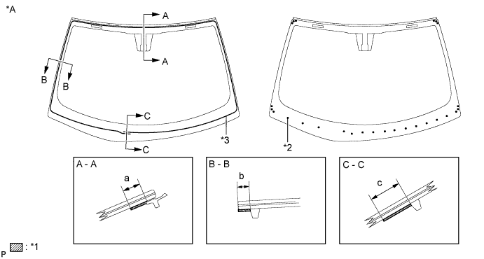
| *A | Back Side | - | - |
| *1 | Primer G | *2 | Ceramic Notch |
| *3 | Adhesive Center | - | - |
| Area | Dimension |
| a | 11.0 mm (0.433 in.) or more |
| b | 15.0 mm (0.591 in.) or more |
| c | 19.0 mm (0.748 in.) or more |
Apply adhesive to the glass.
|
Cut off the tip of the cartridge nozzle as shown in the illustration.
| *1 | Nozzle |
| Area | Dimension |
| a | 8.0 mm (0.315 in.) or more |
| b | 12.0 mm (0.472 in.) or more |
| Temperature | Usage Time Frame |
| 35°C (95°F) | 15 minutes |
| 20°C (68°F) | 1 hour and 40 minutes |
| 5°C (41°F) | 8 hours |
Load the sealer gun with the cartridge.
Apply adhesive to the windshield glass sub-assembly as shown in the illustration.
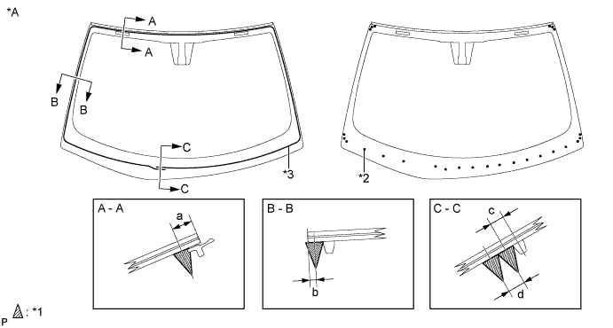
| *A | Back Side | - | - |
| *1 | Adhesive | *2 | Ceramic Notch |
| *3 | Adhesive Center | - | - |
| Area | Dimension |
| a | 9.7 to 10.7 mm (0.382 to 0.421 in.) |
| b | 3.0 mm (0.118 in.) |
| c | 6.5 mm (0.256 in.) |
| d | 8.0 mm (0.315 in.) |
|
Install the windshield glass sub-assembly.
| *1 | Matchmark |
Using suction cups, position the windshield glass so that the matchmarks are aligned, and press it in gently along the rim.
Lightly press the front surface of the windshield glass sub-assembly to ensure that the windshield glass is securely fit to the vehicle body.
|
Using a scraper, remove any excess or protruding adhesive.
| *1 | Dam |
| *2 | Adhesive |
| *3 | Windshield |
Hold the windshield glass using protective tape until the applied adhesive becomes hard.
| Temperature | Minimum Time prior to Driving Vehicle |
| 35°C (95°F) | 1 hour and 30 minutes |
| 20°C (68°F) | 5 hours |
| 5°C (41°F) | 24 hours |
w/ Front Window Deicer System:
Engage the 3 clamps.
Connect the connector.
| 8. INSPECT FOR LEAK AND REPAIR |
After the adhesive has hardened, apply water from the outside of the vehicle. Check that no water leaks into the cabin.
If water leaks into the cabin, allow the water to dry and add adhesive.
Remove the protective tape.
| 9. INSTALL ROOF HEADLINING ASSEMBLY |
Return the front section of the roof headlining assembly to the original position.
| 10. INSTALL SLIDING ROOF OPENING TRIM MOULDING (w/ Sliding Roof) |
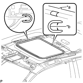 |
Align the alignment mark (green) on the moulding with the notch of the roof headlining to install the sliding roof opening trim moulding.
| *a | Notch |
| *b | Alignment Mark (Green) |
| 11. INSTALL VISOR HOLDER |
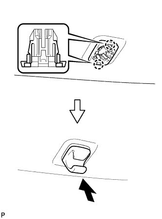 |
Engage the 2 claws.
Push in the visor holder as shown in the illustration.
| 12. INSTALL VISOR ASSEMBLY LH |
Install the visor assembly LH with the 2 screws.
| 13. INSTALL VISOR BRACKET COVER (for LH Side) |
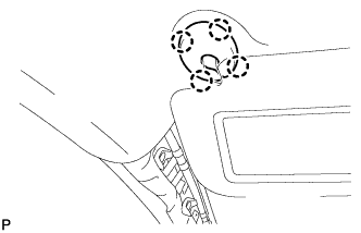 |
Engage the 4 claws to install the visor bracket cover LH.
| 14. INSTALL VISOR ASSEMBLY RH |
| 15. INSTALL VISOR BRACKET COVER (for RH Side) |
| 16. INSTALL ASSIST GRIP SUB-ASSEMBLY |
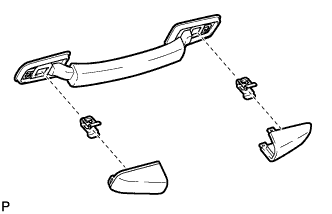 |
Assemble the assist grip sub-assembly as shown in the illustration.
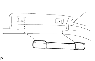 |
Install the assist grip sub-assembly.
| 17. INSTALL NO. 1 ROOM LIGHT ASSEMBLY |
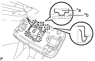 |
Align the switch parts shown in the illustration and engage the 4 claws to install the room light switch base to the No. 1 room light housing.
| *a | Switch Part of Room Light Switch Base |
| *b | Switch Part of No. 1 Room Light Housing |
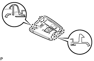 |
Engage the 4 claws to install the No. 1 room light housing.
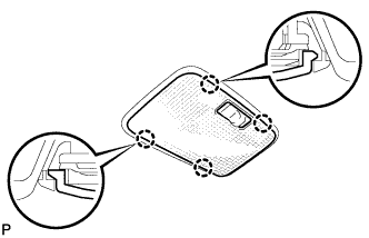 |
Engage the 4 claws to install the No. 1 room light lens.
| 18. INSTALL MAP LIGHT ASSEMBLY |
Connect the connector.
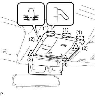 |
Engage the 3 guides and 4 clips to install the map light assembly as shown in the illustration.
Close the overhead console.
| 19. INSTALL FRONT PILLAR GARNISH LH |
Remove the protective cover.
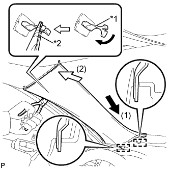 |
Make sure that the front pillar garnish clip is not damaged.
| *1 | Front Pillar Garnish Clip |
| *2 | Protective Tape |
Engage the 2 guides by moving the garnish in the direction indicated by the arrow (1).
Turn the end of the front pillar garnish clip 90° with needle-nosed pliers and install it to the front pillar garnish LH.
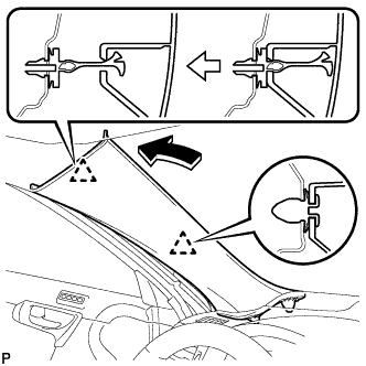 |
Engage the 2 clips to install the front pillar garnish LH.
| 20. INSTALL FRONT DOOR OPENING TRIM WEATHERSTRIP LH |
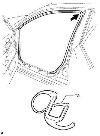 |
Align the alignment mark (orange) on the weatherstrip with the protruding portion on the body indicated by the arrow in the illustration, and install the front door opening trim weatherstrip LH.
| *a | Alignment Mark (Orange) |
| 21. INSTALL FRONT PILLAR GARNISH RH |
| 22. INSTALL FRONT DOOR OPENING TRIM WEATHERSTRIP RH |
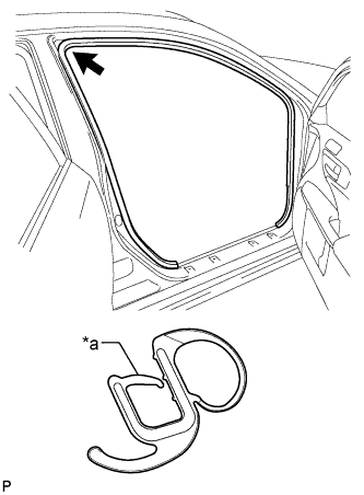 |
Align the alignment mark (light blue) on the weatherstrip with the protruding portion on the body indicated by the arrow in the illustration, and install the front door opening trim weatherstrip RH.
| *a | Alignment Mark (Light blue) |
| 23. INSTALL HUMIDITY SENSOR (w/ Humidity Sensor) |
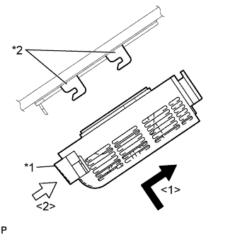 |
Engage the 2 guides, and carefully install the humidity sensor to the glass surface, preventing air bubbles from forming between the contact surfaces.
| *1 | Stopper |
| *2 | Bracket |
Push in the stopper.
Connect the connector.
| 24. INSTALL PROTECTOR (w/ Humidity Sensor) |
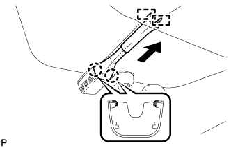 |
Engage the 2 claws and temporarily install the protector.
Slide the protector and engage the 2 guides as shown in the illustration to install the protector.
| 25. INSTALL RAIN SENSOR TAPE (w/ Rain Sensor) |
Clean the rain sensor sensing portion with a piece of cloth, etc.
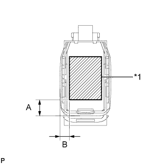 |
Peel off the smaller release sheet, and then attach the rain sensor tape on the rain sensor sensing portion as shown in the illustration.
| Area | Measurement |
| A | 13.5 mm (0.532 in.) |
| B | 7.25 mm (0.285 in.) |
| *1 | Rain Sensor Tape |
| 26. INSTALL RAIN SENSOR (w/ Rain Sensor) |
Clean the windshield glass with a piece of cloth, etc.
When installing a new rain sensor or replacing the rain sensor tape:
Peel off the release sheet.
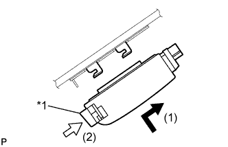 |
Gradually attach the rain sensor to the glass surface to prevent air bubbles from forming between them.
Push in the stopper.
| *1 | Stopper |
Connect the connector.
| 27. INSTALL RAIN SENSOR COVER (w/ Rain Sensor) |
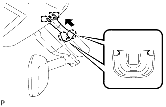 |
Engage the 2 claws and connect the rain sensor cover.
Engage the 2 guides and install the rain sensor cover as shown in the illustration.
| 28. INSTALL INNER REAR VIEW MIRROR ASSEMBLY (w/o EC Mirror) |
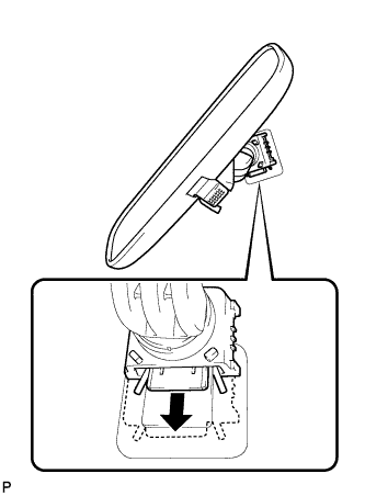 |
Slide the inner rear view mirror assembly in the direction indicated by the arrow in the illustration to install it.
Engage the 2 claws to the inner mirror base cover.
| 29. INSTALL INNER REAR VIEW MIRROR ASSEMBLY (w/ EC Mirror) |
Using a T20 "TORX" socket wrench, install the inner rear view mirror assembly with the screw.
Connect the connector.
| 30. INSTALL INNER REAR VIEW MIRROR STAY HOLDER COVER (w/ EC Mirror) |
w/o Rear View Monitor System:
Engage the 6 claws to install the inner rear view mirror stay holder cover.
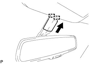 |
Engage the 2 guides to install the inner rear view mirror stay holder cover as shown in the illustration.
w/ Rear View Monitor System:
Engage the 2 claws to install the inner rear view mirror stay holder cover.
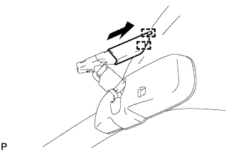 |
Engage the 2 guides to install the inner rear view mirror stay holder cover as shown in the illustration.
| 31. CLEAN WINDSHIELD GLASS (w/ Rain Sensor) |
When reusing the windshield glass:
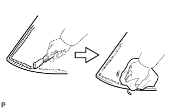 |
Using a scraper, remove any adhesive tape and adhesive residue from the windshield glass.
Clean the outer circumference of the windshield glass with a non-residue solvent.
| 32. INSTALL WINDSHIELD OUTSIDE MOULDING LH |
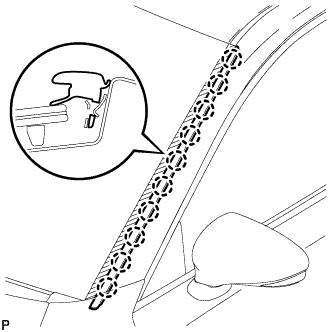 |
Engage the guide and 10 claws to install the windshield outside moulding.
| 33. INSTALL WINDSHIELD OUTSIDE MOULDING RH |
| 34. INSTALL COWL TOP VENTILATOR LOUVER SUB-ASSEMBLY |
Engage the 7 guides as shown in the illustration.
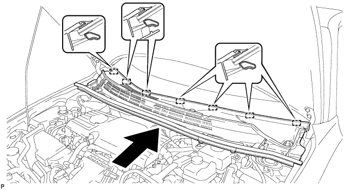
Engage the 6 claws and guide to install the cowl top ventilator louver sub-assembly as shown in the illustration.
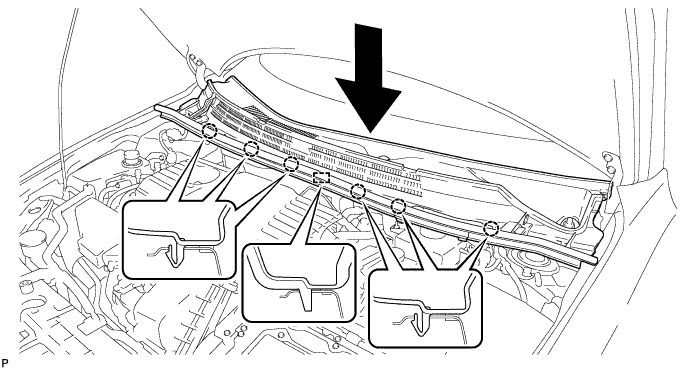
Install the 2 clips.
| 35. INSTALL FRONT NO. 2 SIDE PANEL PROTECTOR LH |
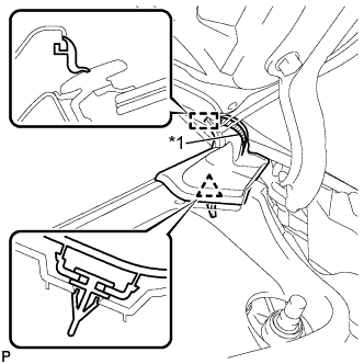 |
Wipe off any tape adhesive residue with cleaner.
| *1 | Double-sided Tape |
Remove the release paper from a new front No. 2 side panel protector LH.
Engage the guide and clip to install the front No. 2 side panel protector LH as shown in the illustration.
| 36. INSTALL FRONT NO. 2 SIDE PANEL PROTECTOR RH |
| 37. INSTALL FRONT WIPER ARM AND BLADE ASSEMBLY LH |
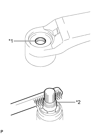 |
When reusing the front wiper arm and blade assembly LH:
Clean the wiper arm serrations.
| *1 | Wiper Arm Serration |
| *2 | Wiper Pivot Serration |
When reusing the windshield wiper link assembly:
Clean the wiper pivot serrations with a wire brush.
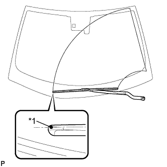 |
Install the front wiper arm and blade assembly LH with the nut to the position shown in the illustration.
| *1 | Ceramic Dot |
| 38. INSTALL FRONT WIPER ARM AND BLADE ASSEMBLY RH |
|
When reusing the front wiper arm and blade assembly RH:
Clean the wiper arm serrations.
| *1 | Wiper Arm Serration |
| *2 | Wiper Pivot Serration |
When reusing the windshield wiper link assembly:
Clean the wiper pivot serrations with a wire brush.
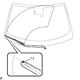 |
Install the front wiper arm and blade assembly RH with the nut to the position shown in the illustration.
| *1 | Ceramic Dot |
Turn the power switch on (IG).
Operate the front wiper while spraying washer fluid onto the windshield glass. Make sure that the front wiper functions properly and the wiper does not come into contact with the vehicle body.
Lift each wiper arm twice after the wipers stop and check the wiper set position.
Turn the power switch off.
| 39. INSTALL FRONT WIPER ARM HEAD CAP |
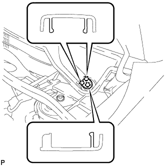 |
Engage the 3 claws to install the front wiper arm head cap.
