DTC P0AA6-526 Hybrid Battery Voltage System Isolation Fault |
DTC P0AA6-611 Hybrid Battery Voltage System Isolation Fault |
DTC P0AA6-612 Hybrid Battery Voltage System Isolation Fault |
DTC P0AA6-613 Hybrid Battery Voltage System Isolation Fault |
DTC P0AA6-614 Hybrid Battery Voltage System Isolation Fault |
| DTC No. | INF Code | DTC Detection Condition | Trouble Area |
| P0AA6 | 526(*1) | Insulation resistance between the high-voltage circuit and the body has decreased. |
|
| P0AA6 | 611 | Insulation resistance of the compressor with motor assembly has decreased. | Compressor with motor assembly |
| P0AA6 | 612 | Insulation resistance of the HV battery area has decreased. |
|
| P0AA6 | 613 | Insulation resistance of the transaxle area has decreased. |
|
| P0AA6 | 614 | Insulation resistance of the high-voltage DC area has decreased. |
|
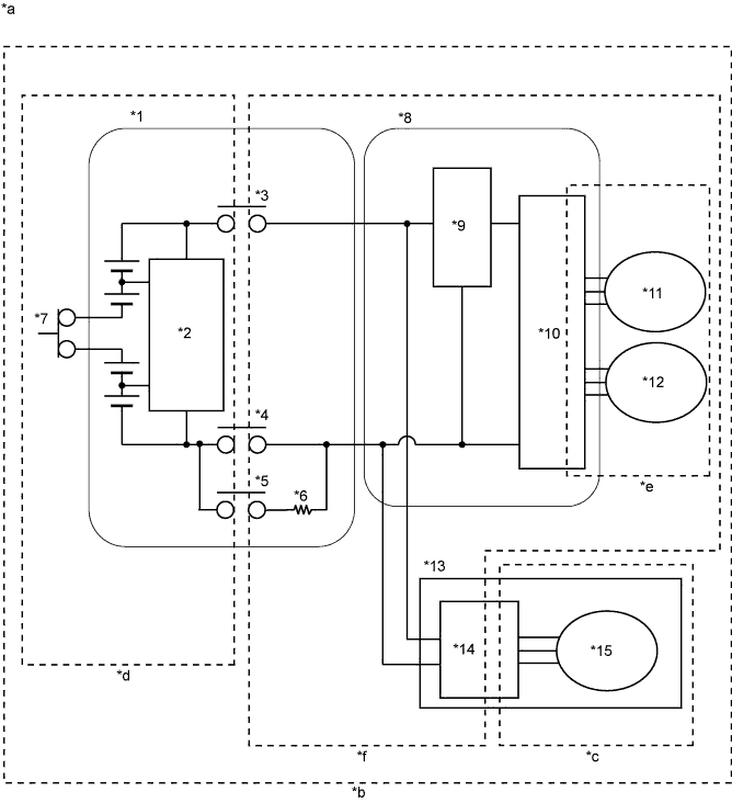
| *1 | HV Battery | *2 | Battery Smart Unit |
| *3 | SMRB | *4 | SMRG |
| *5 | SMRP | *6 | System Main Resistor |
| *7 | Service Plug Grip | *8 | Inverter with Converter Assembly |
| *9 | Boost Converter | *10 | Inverter |
| *11 | MG1 | *12 | MG2 |
| *13 | Compressor with Motor Assembly | *14 | A/C Inverter |
| *15 | A/C Motor | - | - |
| *a | High-voltage Areas | *b | INF Code 526 Vehicle Insulation Resistance Reduction Area |
| *c | INF Code 611 Air Conditioning Area | *d | INF Code 612 HV Battery Area |
| *e | INF Code 613 Transaxle Area | *f | INF Code 614 High Voltage Direct Current Area |
| Characteristics of Short Wave Highest Value |
The Data List item Short Wave Highest Val and insulation resistance have the relationship shown in the table below. Short Wave Highest Val decreases with a decrease in insulation resistance. However, in some cases, even though the insulation resistance of the vehicle is normal, Short Wave Highest Val may decrease. Therefore, check Short Wave Highest Val while considering the following.
| Short Wave Highest Value | Trouble Area |
| Neither condition (*1) nor (*2) is met and Short Wave Highest Val is approximately 0 V | Since the insulation resistance is close to 0 Ω, there is a strong possibility of interference with a metal object. |
| Neither condition (*1) nor (*2) is met and Short Wave Highest Val is between 0 and 5 V | Since the insulation resistance is several hundred kiloohms, there is a strong possibility of the presence of fluid such as coolant. |
| How to Determine Part with Insulation Malfunction |
Jiggle the high-voltage wire harness to check if the resistance to body ground changes with the position of the wire harness or force applied.
Repeat rotating and stopping of the MG1, MG2 and compressor with motor. Check that the Short Wave Highest Val does not decrease (for example if the motor stops with foreign matter forming a leak path) when the motor stops, or that the Short Wave Highest Val does not return to normal (for example if foreign matter moves away from the leak path) when the motor rotates.
Increase the temperature of MG1and MG2. Check if the Short Wave Highest Val decreases with the temperature increase.
| 1.CHECK DTC OUTPUT (HV) |
Connect the intelligent tester to the DLC3.
Turn the power switch on (IG).
Enter the following menus: Powertrain / Hybrid Control / DTC.
Check if DTCs are output.
| Result | Proceed to |
| P0AA6 only is output. | A |
| P0AA6 and P0A1D (power management control ECU malfunction) are output. | B |
| P0AA6 and P0AA7 (malfunction in the battery smart unit) are output. | C |
| P0AA6 and P0AFC (battery ECU malfunction) are output. | D |
Turn the power switch off.
|
| ||||
|
| ||||
|
| ||||
| A | |
 |
| 2.CHECK INFORMATION CODE |
Enter the following menus: Powertrain / Hybrid Control / DTC.
Access the freeze frame data of DTC P0AA6 and read the INF code.
| Result | Proceed to |
| 526 (decrease in the insulation resistance of the high-voltage circuit) only is output | A |
| 526 and 611 (decrease in the insulation resistance of the air conditioning area) are output | Refer to the troubleshooting procedures for P0AA6-611 (Heater and air conditioning system) (Click here) |
| 526 and 612 (decrease in the insulation resistance of the battery area) are output | B |
| 526 and 613 (decrease in the insulation resistance of the transaxle area) are output | C |
| 526 and 614 (decrease in the insulation resistance of the high-voltage DC area) are output | D |
|
| ||||
|
| ||||
|
| ||||
| A | |
|
| 3.CHECK HYBRID VEHICLE TRANSAXLE ASSEMBLY (MOTOR CABLE) |
Turn the power switch off.
Check that the service plug grip is not installed.
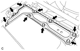 |
Remove the inverter cover from the inverter with converter assembly.
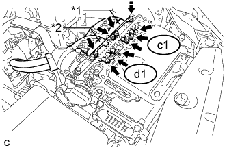 |
Disconnect the motor cable c1 and generator cable d1 from the inverter with converter assembly.
| *1 | Motor Cable |
| *2 | Generator Cable |
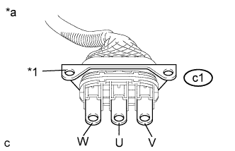 |
Using a megohmmeter set to 500 V, measure the resistance according to the value(s) in the table below.
| Tester Connection | Switch Condition | Specified Condition |
| c1-3 (V) - Body ground and shielded wire ground | Power switch off | 100 MΩ or higher |
| c1-2 (U) - Body ground and shielded wire ground | Power switch off | 100 MΩ or higher |
| c1-1 (W) - Body ground and shielded wire ground | Power switch off | 100 MΩ or higher |
| *1 | Shielded Wire Ground |
| *a | Front view of Motor Cable connector (to Inverter with Converter Assembly) |
|
| ||||
| OK | |
|
| 4.CHECK HYBRID VEHICLE TRANSAXLE ASSEMBLY (GENERATOR CABLE) |
Check that the service plug grip is not installed.
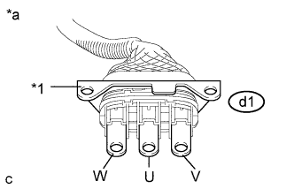 |
Using a megohmmeter set to 500 V, measure the resistance according to the value(s) in the table below.
| Tester Connection | Switch Condition | Specified Condition |
| d1-3 (V) - Body ground and shielded wire ground | Power switch off | 100 MΩ or higher |
| d1-2 (U) - Body ground and shielded wire ground | Power switch off | 100 MΩ or higher |
| d1-1 (W) - Body ground and shielded wire ground | Power switch off | 100 MΩ or higher |
| *1 | Shielded Wire Ground |
| *a | Front view of Generator Cable connector (to Inverter with Converter Assembly) |
|
| ||||
| OK | |
|
| 5.CHECK NO. 2 ENGINE WIRE |
Check that the service plug grip is not installed.
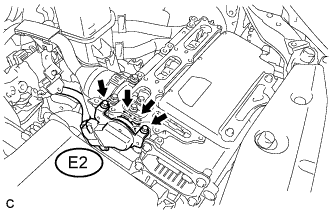 |
Disconnect the No. 2 engine wire (air conditioning harness) E2 from the inverter with converter assembly.
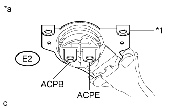 |
Using a megohmmeter set to 500 V, measure the resistance according to the value(s) in the table below.
| Tester Connection | Switch Condition | Specified Condition |
| E2-1 (ACPB) - Body ground and shielded wire ground | Power switch off | 3 MΩ or higher |
| E2-2 (ACPE) - Body ground and shielded wire ground | Power switch off | 3 MΩ or higher |
| *1 | Shielded Wire Ground |
| *a | Front view of No. 2 Engine Wire (Air Conditioning Harness) connector (to Inverter with Converter Assembly) |
|
| ||||
| OK | |
|
| 6.CHECK INVERTER WITH CONVERTER ASSEMBLY |
Check that the service plug grip is not installed.
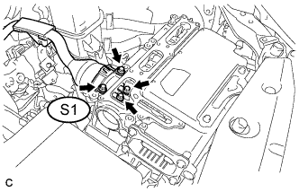 |
Disconnect the frame wire S1 from the inverter with converter assembly.
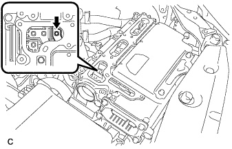 |
Using a megohmmeter set to 500 V, measure the resistance according to the value(s) in the table below.
| Tester Connection | Switch Condition | Specified Condition |
| High voltage terminal - Body ground | Power switch off | 1 MΩ or higher |
|
| ||||
| OK | |
|
| 7.CHECK FRAME WIRE |
Check that the service plug grip is not installed.
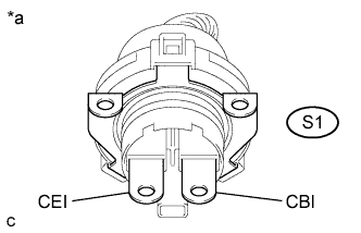 |
Using a megohmmeter set to 500 V, measure the resistance according to the value(s) in the table below.
| Tester Connection | Switch Condition | Specified Condition |
| S1-1 (CEI) - Body ground | Power switch off | 10 MΩ or higher |
| S1-2 (CBI) - Body ground | Power switch off | 10 MΩ or higher |
| *a | Front view of Frame Wire connector (to Inverter with Converter Assembly) |
|
| ||||
| OK | |
|
| 8.CHECK HV BATTERY AREA |
Turn the power switch off.
Check that the service plug grip is not installed.
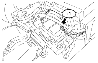 |
Disconnect connector i1 from the battery smart unit.
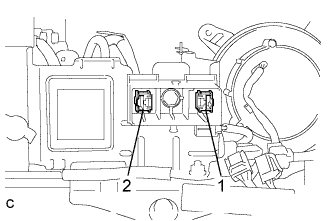 |
Using a megohmmeter set to 500 V, measure the resistance according to the value(s) in the table below.
| Tester Connection | Switch Condition | Specified Condition |
| 1 - Body ground | Power switch off | 10 MΩ or higher |
| 2 - Body ground | Power switch off | 10 MΩ or higher |
|
| ||||
| OK | ||
 | ||
| ||
| 9.CHECK INVERTER WITH CONVERTER ASSEMBLY |
Turn the power switch off.
Check that the service plug grip is not installed.
|
Remove the inverter cover from the inverter with converter assembly.
|
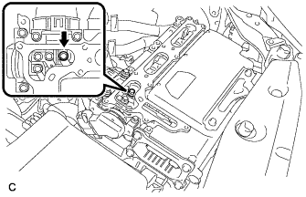
Disconnect the motor cable c1 and generator cable d1 from the inverter with converter assembly.
| *1 | Motor Cable |
| *2 | Generator Cable |
 |
Using a megohmmeter set to 500 V, measure the resistance according to the value(s) in the table below.
| Tester Connection | Switch Condition | Specified Condition |
| High voltage terminal - Body ground | Power switch off | 1 MΩ or higher |
| Result | Proceed to |
| NG | A |
| OK | B |
|
| ||||
| A | ||
| ||
| ||
| 10.CHECK HYBRID VEHICLE TRANSAXLE ASSEMBLY (MOTOR CABLE) |
Turn the power switch off.
Check that the service plug grip is not installed.
|
Remove the inverter cover from the inverter with converter assembly.
|
Disconnect the motor cable c1 and generator cable d1 from the inverter with converter assembly.
| *1 | Motor Cable |
| *2 | Generator Cable |
|
Using a megohmmeter set to 500 V, measure the resistance according to the value(s) in the table below.
| Tester Connection | Switch Condition | Specified Condition |
| c1-3 (V) - Body ground and shielded wire ground | Power switch off | 100 MΩ or higher |
| c1-2 (U) - Body ground and shielded wire ground | Power switch off | 100 MΩ or higher |
| c1-1 (W) - Body ground and shielded wire ground | Power switch off | 100 MΩ or higher |
| *1 | Shielded Wire Ground |
| *a | Front view of Motor Cable connector (to Inverter with Converter Assembly) |
|
| ||||
| OK | |
|
| 11.CHECK HYBRID VEHICLE TRANSAXLE ASSEMBLY (GENERATOR CABLE) |
Check that the service plug grip is not installed.
|
Using a megohmmeter set to 500 V, measure the resistance according to the value(s) in the table below.
| Tester Connection | Switch Condition | Specified Condition |
| d1-3 (V) - Body ground and shielded wire ground | Power switch off | 100 MΩ or higher |
| d1-2 (U) - Body ground and shielded wire ground | Power switch off | 100 MΩ or higher |
| d1-1 (W) - Body ground and shielded wire ground | Power switch off | 100 MΩ or higher |
| *1 | Shielded Wire Ground |
| *a | Front view of Generator Cable connector (to Inverter with Converter Assembly) |
|
| ||||
| OK | |
|
| 12.CHECK HIGH VOLTAGE DIRECT CURRENT AREA |
Turn the power switch off.
Check that the service plug grip is not installed.
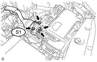 |
Disconnect the frame wire S1 from the inverter with converter assembly.
|
Using a megohmmeter set to 500 V, measure the resistance according to the value(s) in the table below.
| Tester Connection | Switch Condition | Specified Condition |
| S1-1 (CEI) - Body ground | Power switch off | 10 MΩ or higher |
| S1-2 (CBI) - Body ground | Power switch off | 10 MΩ or higher |
| *a | Front view of Frame Wire connector (to Inverter with Converter Assembly) |
|
| ||||
| OK | |
|
| 13.CHECK NO. 2 ENGINE WIRE |
Check that the service plug grip is not installed.
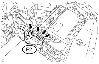 |
Disconnect the No. 2 engine wire (air conditioning harness) E2 from the inverter with converter assembly.
|
Using a megohmmeter set to 500 V, measure the resistance according to the value(s) in the table below.
| Tester Connection | Switch Condition | Specified Condition |
| E2-1 (ACPB) - Body ground and shielded wire ground | Power switch off | 3 MΩ or higher |
| E2-2 (ACPE) - Body ground and shielded wire ground | Power switch off | 3 MΩ or higher |
| *1 | Shielded Wire Ground |
| *a | Front view of No. 2 Engine Wire (Air Conditioning Harness) connector (to Inverter with Converter Assembly) |
|
| ||||
| OK | ||
| ||
| ||
| 14.CHECK NO. 2 ENGINE WIRE |
Check that the service plug grip is not installed.
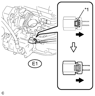 |
Disconnect the No. 2 engine wire (air conditioning harness) E1 from the compressor with motor assembly.
| *1 | Green Lock |
|
Using a megohmmeter set to 500 V, measure the resistance according to the value(s) in the table below.
| Tester Connection | Switch Condition | Specified Condition |
| E2-1 (ACPB) - Body ground and shielded wire ground | Power switch off | 10 MΩ or higher |
| E2-2 (ACPE) - Body ground and shielded wire ground | Power switch off | 10 MΩ or higher |
| *1 | Shielded Wire Ground |
| *a | Front view of No. 2 Engine Wire (Air Conditioning Harness) connector (to Inverter with Converter Assembly) |
|
| ||||
| OK | ||
| ||
| ||
| 15.CHECK FRAME WIRE |
Check that the service plug grip is not installed.
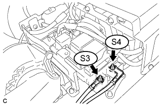 |
Disconnect the frame wire S4 and S3 from the hybrid battery junction block assembly.
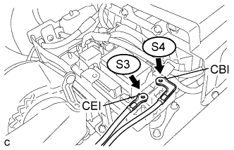 |
Using a megohmmeter set to 500 V, measure the resistance according to the value(s) in the table below.
| Tester Connection | Switch Condition | Specified Condition |
| S4-1 (CBI) - Body ground and shielded wire ground | Power switch off | 10 MΩ or higher |
| S3-1 (CEI) - Body ground and shielded wire ground | Power switch off | 10 MΩ or higher |
|
| ||||
| OK | ||
| ||
| ||
| 16.CHECK HYBRID BATTERY JUNCTION BLOCK ASSEMBLY |
Check that the service plug grip is not installed.
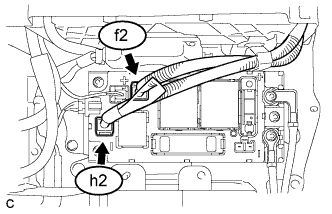 |
Disconnect the high voltage cable connector of the HV battery f2 and h2 from the hybrid battery junction block assembly.
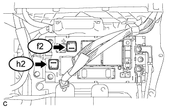 |
Using a megohmmeter set to 500 V, measure the resistance according to the value(s) in the table below.
| Tester Connection | Switch Condition | Specified Condition |
| h2-1 (-) - Hybrid Battery Carrier Panel | Power switch off | 10 MΩ or higher |
| f2-1 (+) - Hybrid Battery Carrier Panel | Power switch off | 10 MΩ or higher |
|
| ||||
| OK | ||
| ||
| ||
| 17.CHECK MOTOR CABLE |
Turn the power switch off.
Check that the service plug grip is not installed.
Disconnect the motor cable from the hybrid vehicle transaxle assembly (Click here).
|
Using a megohmmeter set to 500 V, measure the resistance according to the value(s) in the table below.
| Tester Connection | Switch Condition | Specified Condition |
| c1-3 (V) - Body ground and shielded wire ground | Power switch off | 100 MΩ or higher |
| c1-2 (U) - Body ground and shielded wire ground | Power switch off | 100 MΩ or higher |
| c1-1 (W) - Body ground and shielded wire ground | Power switch off | 100 MΩ or higher |
| *1 | Shielded Wire Ground |
| *a | Front view of Motor Cable connector (to Inverter with Converter Assembly) |
|
| ||||
| OK | ||
| ||
| ||
| 18.CHECK GENERATOR CABLE |
Check that the service plug grip is not installed.
Disconnect the generator cable from the hybrid vehicle transaxle assembly (Click here).
|
Using a megohmmeter set to 500 V, measure the resistance according to the value(s) in the table below.
| Tester Connection | Switch Condition | Specified Condition |
| d1-3 (V) - Body ground and shielded wire ground | Power switch off | 100 MΩ or higher |
| d1-2 (U) - Body ground and shielded wire ground | Power switch off | 100 MΩ or higher |
| d1-1 (W) - Body ground and shielded wire ground | Power switch off | 100 MΩ or higher |
| *1 | Shielded Wire Ground |
| *a | Front view of Generator Cable connector (to Inverter with Converter Assembly) |
|
| ||||
| OK | ||
| ||
| ||
| 19.CHECK MOTOR CABLE |
Turn the power switch off.
Check that the service plug grip is not installed.
Disconnect the motor cable from the hybrid vehicle transaxle assembly (Click here).
|
Using a megohmmeter set to 500 V, measure the resistance according to the value(s) in the table below.
| Tester Connection | Switch Condition | Specified Condition |
| c1-3 (V) - Body ground and shielded wire ground | Power switch off | 100 MΩ or higher |
| c1-2 (U) - Body ground and shielded wire ground | Power switch off | 100 MΩ or higher |
| c1-1 (W) - Body ground and shielded wire ground | Power switch off | 100 MΩ or higher |
| *1 | Shielded Wire Ground |
| *a | Front view of Motor Cable connector (to Inverter with Converter Assembly) |
|
| ||||
| OK | |
|
| 20.CHECK GENERATOR CABLE |
Check that the service plug grip is not installed.
Disconnect the generator cable from the hybrid vehicle transaxle assembly (Click here).
|
Using a megohmmeter set to 500 V, measure the resistance according to the value(s) in the table below.
| Tester Connection | Switch Condition | Specified Condition |
| d1-3 (V) - Body ground and shielded wire ground | Power switch off | 100 MΩ or higher |
| d1-2 (U) - Body ground and shielded wire ground | Power switch off | 100 MΩ or higher |
| d1-1 (W) - Body ground and shielded wire ground | Power switch off | 100 MΩ or higher |
| *1 | Shielded Wire Ground |
| *a | Front view of Generator Cable connector (to Inverter with Converter Assembly) |
|
| ||||
| OK | ||
| ||
| ||


