DTC U0110-159 Lost Communication with Driver Motor Control Module |
DTC U0110-656 Lost Communication with Driver Motor Control Module |
DTC U0110-657 Lost Communication with Driver Motor Control Module |
| DTC No. | INF Code | DTC Detection Condition | Trouble Area |
| U0110 | 159 | Error in reception from inverter with converter assembly (MG ECU) via serial communication (out of communication standard) |
|
| U0110 | 656 | Error in reception from inverter with converter assembly (MG ECU) via serial communication (out of communication standard) | |
| U0110 | 657 | Error in reception from inverter with converter assembly (MG ECU) via serial communication (no reception) |
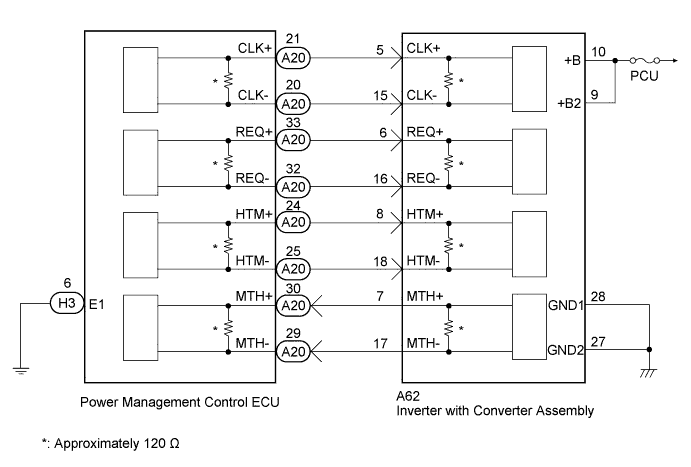
| 1.CHECK FUSE (PCU) |
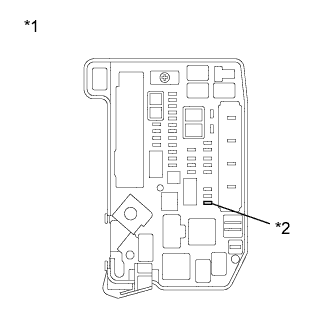
Remove the PCU fuse from the engine room junction block assembly.
 |
Measure the resistance according to the value(s) in the table below.
| Tester Connection | Switch Condition | Specified Condition |
| PCU fuse terminals | Always | Below 1 Ω |
| *1 | Engine Room Junction Block Assembly |
| *2 | PCU Fuse |
Install the PCU fuse.
|
| ||||
| OK | |
 |
| 2.CLEAR DTC |
Connect the intelligent tester to the DLC3.
Turn the power switch on (IG).
Enter the following menus: Powertrain / Hybrid Control / DTC.
Clear DTCs and freeze frame data.
| NEXT | |
|
| 3.CHECK DTC OUTPUT (HYBRID CONTROL) |
Connect the intelligent tester to the DLC3.
Turn the power switch on (IG).
Enter the following menus: Powertrain / Hybrid Control / DTC.
Check if DTCs are output.
| Result | Proceed to |
| DTC U0110-159, 656 or 657 is output. | A |
| DTC U0110-159, 656 and 657 are not output. | B |
Turn the power switch off.
|
| ||||
| A | |
|
| 4.CHECK INVERTER WITH CONVERTER ASSEMBLY (GENERATOR CABLE CONNECTION CONDITION) |
Check that the service plug grip is not installed.
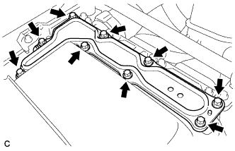 |
Remove the inverter cover from the inverter with converter assembly.
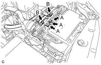 |
Check that the bolts for the generator cable are tightened to the specified torque, the generator cable is connected securely, and there are no contact problems.
Disconnect the generator cable from the inverter with converter assembly.
Check for arc marks at the bolts for the generator cable.
| Result | Proceed to | |
| The terminals are connected securely and there are no contact problems. | There are no arc marks. | A |
| The terminals are not connected securely and there is a contact problem. | There are arc marks. | B |
| The terminals are not connected securely and there is a contact problem. | There are no arc marks. | C |
| The terminals are connected securely and there are no contact problems. | There are arc marks. | B |
Connect the generator cable to the inverter with converter assembly.
Install the inverter cover.
|
| ||||
|
| ||||
| A | |
|
| 5.CHECK INVERTER WITH CONVERTER ASSEMBLY (MOTOR CABLE CONNECTION CONDITION) |
Check that the service plug grip is not installed.
|
Remove the inverter cover from the inverter with converter assembly.
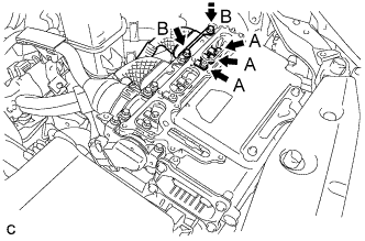 |
Check that the bolts for the motor cable are tightened to the specified torque, the motor cable is connected securely, and there are no contact problems.
Disconnect the motor cable from the inverter with converter assembly.
Check for arc marks at the bolts for the motor cable.
| Result | Proceed to | |
| The terminals are connected securely and there are no contact problems. | There are no arc marks. | A |
| The terminals are not connected securely and there is a contact problem. | There are arc marks. | B |
| The terminals are not connected securely and there is a contact problem. | There are no arc marks. | C |
| The terminals are connected securely and there are no contact problems. | There are arc marks. | B |
Connect the motor cable to the inverter with converter assembly.
Install the inverter cover.
|
| ||||
|
| ||||
| A | |
|
| 6.CHECK HYBRID VEHICLE TRANSAXLE ASSEMBLY (MG1) |
Check that the service plug grip is not installed.
|
Remove the inverter cover from the inverter with converter assembly.
Disconnect the generator cable and motor cable from the inverter with converter assembly.
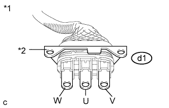 |
Check MG1 for an interphase short using a milliohmmeter.
Using a milliohmmeter, measure the resistance according to the value(s) in the table below.
| Tester Connection | Switch Condition | Specified Condition |
| d1-1 (W) - d1-2 (U) | Power switch off | 89.5 to 98.9 mΩ |
| d1-2 (U) - d1-3 (V) | Power switch off | 89.5 to 98.9 mΩ |
| d1-3 (V) - d1-1 (W) | Power switch off | 89.5 to 98.9 mΩ |
| *1 | Generator Cable |
| *2 | Shield Ground |
Using a megohmmeter set to 500 V, measure the resistance according to the value(s) in the table below.
| Tester Connection | Switch Condition | Specified Condition |
| d1-1 (W) - Body ground and shield ground | Power switch off | 100 MΩ or higher |
| d1-2 (U) - Body ground and shield ground | Power switch off | 100 MΩ or higher |
| d1-3 (V) - Body ground and shield ground | Power switch off | 100 MΩ or higher |
Connect the generator cable and motor cable.
Install the inverter cover.
|
| ||||
| OK | |
|
| 7.CHECK HYBRID VEHICLE TRANSAXLE ASSEMBLY (MG2) |
Check that the service plug grip is not installed.
|
Remove the inverter cover from the inverter with converter assembly.
Disconnect the generator cable and motor cable from the inverter with converter assembly.
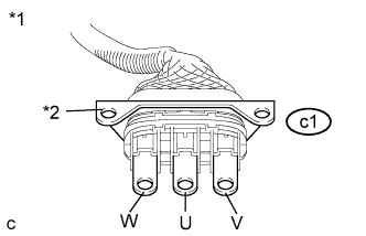 |
Check MG2 for an interphase short using a milliohmmeter.
Using a milliohmmeter, measure the resistance according to the value(s) in the table below.
| Tester Connection | Switch Condition | Specified Condition |
| c1-1 (W) - c1-2 (U) | Power switch off | 152.6 to 169.0 mΩ |
| c1-2 (U) - c1-3 (V) | Power switch off | 157.6 to 174.0 mΩ |
| c1-3 (V) - c1-1 (W) | Power switch off | 151.6 to 168.0 mΩ |
| *1 | Motor Cable |
| *2 | Shield Ground |
Using a megohmmeter set to 500 V, measure the resistance according to the value(s) in the table below.
| Tester Connection | Switch Condition | Specified Condition |
| c1-1 (W) - Body ground and shield ground | Power switch off | 100 MΩ or higher |
| c1-2 (U) - Body ground and shield ground | Power switch off | 100 MΩ or higher |
| c1-3 (V) - Body ground and shield ground | Power switch off | 100 MΩ or higher |
Connect the generator cable and motor cable.
Install the inverter cover.
|
| ||||
| OK | |
|
| 8.CHECK HARNESS AND CONNECTOR (INVERTER WITH CONVERTER ASSEMBLY POWER SOURCE CIRCUIT) |
Turn the power switch off.
Check that the service plug grip is not installed.
Disconnect connector A62 from the inverter with converter assembly.
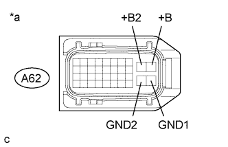 |
Measure the resistance according to the value(s) in the table below.
| Tester Connection | Switch Condition | Specified Condition |
| A62-28 (GND1) - Body ground | Power switch off | Below 1 Ω |
| A62-27 (GND2) - Body ground | Power switch off | Below 1 Ω |
| *a | Front view of wire harness connector (to Inverter with Converter Assembly) |
Turn the power switch on (IG).
Measure the voltage according to the value(s) in the table below.
| Tester Connection | Switch Condition | Specified Condition |
| A62-10 (+B) - Body ground | Power switch on (IG) | 11 to 14 V |
| A62-9 (+B2) - Body ground | Power switch on (IG) | 11 to 14 V |
Turn the power switch off.
Connect the inverter with converter assembly connector.
|
| ||||
| OK | |
|
| 9.CHECK POWER MANAGEMENT CONTROL ECU (CHECK WAVEFORM) |
Connect an oscilloscope between the power management control ECU terminals specified in the following table.
Turn the power switch on (IG).
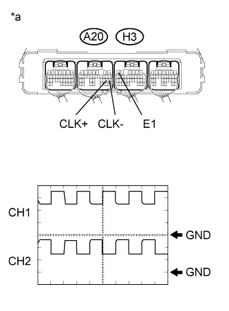 |
Measure the waveform.
| Item | Contents |
| Tester Connection | CH1: A20-21 (CLK+) - H3-6 (E1) CH2: A20-20 (CLK-) - H3-6 (E1) |
| Equipment Setting | 1V/DIV., 1μs/DIV. |
| Condition | Power switch on (IG) |
| Result | Proceed to |
| The waveform appears as shown in the illustration. | A |
| The waveform differs from the one shown in the illustration. | B |
| *a | Component with harness connected (Power Management Control ECU) |
Turn the power switch off.
|
| ||||
| A | |
|
| 10.CHECK POWER MANAGEMENT CONTROL ECU (CHECK WAVEFORM) |
Connect an oscilloscope between the power management control ECU terminals specified in the following table.
Turn the power switch on (IG).
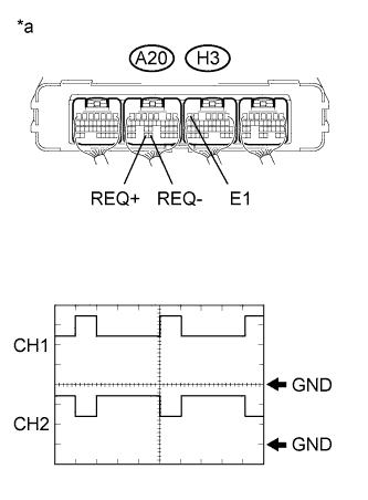 |
Measure the waveform.
| Item | Contents |
| Tester Connection | CH1: A20-33 (REQ+) - H3-6 (E1) CH2: A20-32 (REQ-) - H3-6 (E1) |
| Equipment Setting | 1V/DIV., 1ms/DIV. |
| Condition | Power switch on (IG) |
| Result | Proceed to |
| The waveform appears as shown in the illustration. | A |
| The waveform differs from the one shown in the illustration. | B |
| *a | Component with harness connected (Power Management Control ECU) |
Turn the power switch off.
|
| ||||
| A | |
|
| 11.CHECK POWER MANAGEMENT CONTROL ECU (CHECK WAVEFORM) |
Connect an oscilloscope between the power management control ECU terminals specified in the following table.
Turn the power switch on (IG).
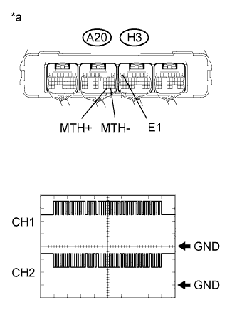 |
Measure the waveform.
| Item | Contents |
| Tester Connection | CH1: A20-30 (MTH+) - H3-6 (E1) CH2: A20-29 (MTH-) - H3-6 (E1) |
| Equipment Setting | 1V/DIV., 200μs/DIV. |
| Condition | Power switch on (IG) |
| Result | Proceed to |
| The waveform appears as shown in the illustration. | A |
| The waveform differs from the one shown in the illustration. | B |
| *a | Component with harness connected (Power Management Control ECU) |
Turn the power switch off.
|
| ||||
| A | ||
 | ||
| ||
| 12.CHECK HARNESS AND CONNECTOR (POWER MANAGEMENT CONTROL ECU - INVERTER WITH CONVERTER) |
Check that the service plug grip is not installed.
Disconnect connector A20 from the power management control ECU.
Disconnect connector A62 from the inverter with converter assembly.
Turn the power switch on (IG).
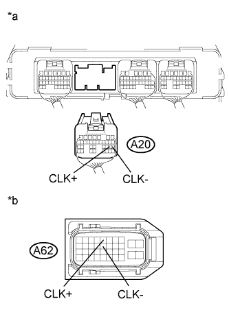 |
Measure the voltage according to the value(s) in the table below.
| Tester Connection | Switch Condition | Specified Condition |
| A20-21 (CLK+) - Body ground | Power switch on (IG) | Below 1 V |
| A20-20 (CLK-) - Body ground | Power switch on (IG) | Below 1 V |
| *a | Rear view of wire harness connector (to Power Management Control ECU) |
| *b | Front view of wire harness connector (to Inverter with Converter Assembly) |
Turn the power switch off.
Measure the resistance according to the value(s) in the table below.
| Tester Connection | Switch Condition | Specified Condition |
| A20-21 (CLK+) - A62-5 (CLK+) | Power switch off | Below 1 Ω |
| A20-20 (CLK-) - A62-15 (CLK-) | Power switch off | Below 1 Ω |
| Tester Connection | Switch Condition | Specified Condition |
| A20-21 (CLK+) or A62-5 (CLK+) - Body ground and other terminals | Power switch off | 10 kΩ or higher |
| A20-20 (CLK-) or A62-15 (CLK-) - Body ground and other terminals | Power switch off | 10 kΩ or higher |
Connect the inverter with converter assembly connector.
Connect the power management control ECU connector.
|
| ||||
| OK | |
|
| 13.CHECK INVERTER WITH CONVERTER ASSEMBLY |
Disconnect connector A20 from the power management control ECU.
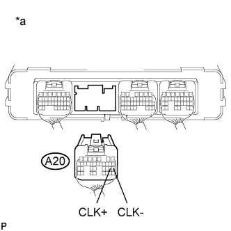 |
Measure the resistance according to the value(s) in the table below.
| Tester Connection | Switch Condition | Specified Condition |
| A20-21 (CLK+) - A20-20 (CLK-) | Power switch off | 80 to 170 Ω |
| *a | Rear view of wire harness connector (to Power Management Control ECU) |
Connect the power management control ECU connector.
|
| ||||
| OK | ||
| ||
| ||
| 14.CHECK HARNESS AND CONNECTOR (POWER MANAGEMENT CONTROL ECU - INVERTER WITH CONVERTER) |
Check that the service plug grip is not installed.
Disconnect connector A20 from the power management control ECU.
Disconnect connector A62 from the inverter with converter assembly.
Turn the power switch on (IG).
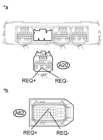 |
Measure the voltage according to the value(s) in the table below.
| Tester Connection | Switch Condition | Specified Condition |
| A20-33 (REQ+) - Body ground | Power switch on (IG) | Below 1 V |
| A20-32 (REQ-) - Body ground | Power switch on (IG) | Below 1 V |
| *a | Rear view of wire harness connector (to Power Management Control ECU) |
| *b | Front view of wire harness connector (to Inverter with Converter Assembly) |
Turn the power switch off.
Measure the resistance according to the value(s) in the table below.
| Tester Connection | Switch Condition | Specified Condition |
| A20-33 (REQ+) - A62-6 (REQ+) | Power switch off | Below 1 Ω |
| A20-32 (REQ-) - A62-16 (REQ-) | Power switch off | Below 1 Ω |
| Tester Connection | Switch Condition | Specified Condition |
| A20-33 (REQ+) or A62-6 (REQ+) - Body ground and other terminals | Power switch off | 10 kΩ or higher |
| A20-32 (REQ-) or A62-16 (REQ-) - Body ground and other terminals | Power switch off | 10 kΩ or higher |
Connect the inverter with converter assembly connector.
Connect the power management control ECU connector.
|
| ||||
| OK | |
|
| 15.CHECK INVERTER WITH CONVERTER ASSEMBLY |
Disconnect connector A20 from the power management control ECU.
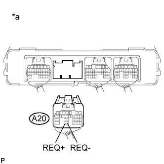 |
Measure the resistance according to the value(s) in the table below.
| Tester Connection | Switch Condition | Specified Condition |
| A20-33 (REQ+) - A20-32 (REQ-) | Power switch off | 80 to 170 Ω |
| *a | Rear view of wire harness connector (to Power Management Control ECU) |
Connect the power management control ECU connector.
|
| ||||
| OK | ||
| ||
| ||
| 16.CHECK HARNESS AND CONNECTOR (POWER MANAGEMENT CONTROL ECU - INVERTER WITH CONVERTER) |
Check that the service plug grip is not installed.
Disconnect connector A20 from the power management control ECU.
Disconnect connector A62 from the inverter with converter assembly.
Turn the power switch on (IG).
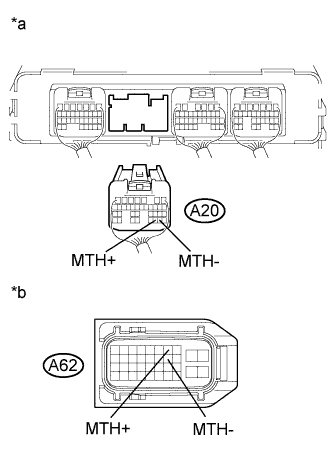 |
Measure the voltage according to the value(s) in the table below.
| Tester Connection | Switch Condition | Specified Condition |
| A20-30 (MTH+) - Body ground | Power switch on (IG) | Below 1 V |
| A20-29 (MTH-) - Body ground | Power switch on (IG) | Below 1 V |
| *a | Rear view of wire harness connector (to Power Management Control ECU) |
| *b | Front view of wire harness connector (to Inverter with Converter Assembly) |
Turn the power switch off.
Measure the resistance according to the value(s) in the table below.
| Tester Connection | Switch Condition | Specified Condition |
| A20-30 (MTH+) - A62-7 (MTH+) | Power switch off | Below 1 Ω |
| A20-29 (MTH-) - A62-17 (MTH-) | Power switch off | Below 1 Ω |
| Tester Connection | Switch Condition | Specified Condition |
| A20-30 (MTH+) or A62-7 (MTH+) - Body ground and other terminals | Power switch off | 10 kΩ or higher |
| A20-29 (MTH-) or A62-17 (MTH-) - Body ground and other terminals | Power switch off | 10 kΩ or higher |
Connect the inverter with converter assembly connector.
Connect the power management control ECU connector.
|
| ||||
| OK | |
|
| 17.CHECK POWER MANAGEMENT CONTROL ECU |
Disconnect connector A62 from the inverter with converter assembly.
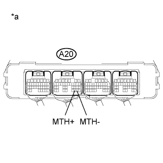 |
Measure the resistance according to the value(s) in the table below.
| Tester Connection | Switch Condition | Specified Condition |
| A20-30 (MTH+) - A20-29 (MTH-) | Power switch off | 80 to 170 Ω |
| *a | Component with harness connected (Power Management Control ECU) |
Connect the inverter with converter assembly connector.
|
| ||||
| OK | ||
| ||
| ||
| 18.REPLACE FUSE (PCU) |
|
Replace the PCU fuse.
| *1 | Engine Room Junction Block Assembly |
| *2 | PCU Fuse |
Turn the power switch on (READY).
Check if there is an open circuit in the PCU fuse in engine room junction block assembly.
Turn the power switch off.
|
| ||||
| OK | ||
| ||
| ||
| 19.CHECK HARNESS AND CONNECTOR (INVERTER WITH CONVERTER ASSEMBLY - PCU FUSE) |
Check that the service plug grip is not installed.
|
Remove the PCU fuse from the engine room junction block assembly.
| *1 | Engine Room Junction Block Assembly |
| *2 | PCU Fuse |
Disconnect connector A62 from the inverter with converter assembly.
Measure the resistance according to the value(s) in the table below.
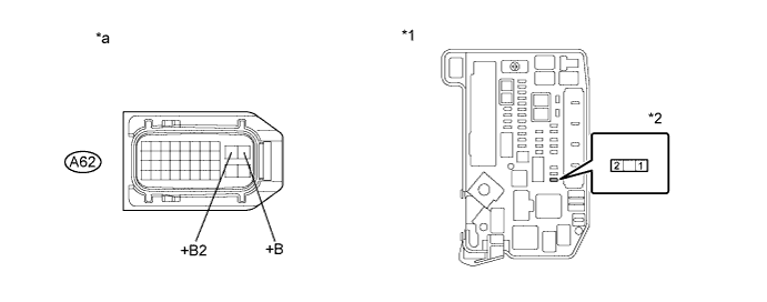
| *1 | Engine Room Junction Block Assembly | *2 | PCU Fuse |
| *a | Front view of wire harness connector (to Inverter with Converter Assembly) | - | - |
| Tester Connection | Switch Condition | Specified Condition |
| A62-10 (+B) - 2 (PCU fuse terminal) | Power switch off | Below 1 Ω |
| A62-9 (+B2) - 2 (PCU fuse terminal) | Power switch off | Below 1 Ω |
| Tester Connection | Switch Condition | Specified Condition |
| A62-10 (+B), A62-9 (+B2) or 2 (PCU fuse terminal) - Body ground and other terminals | Power switch off | 10 kΩ or higher |
Connect the inverter with converter assembly connector.
Install the PCU fuse.
|
| ||||
| OK | |
|
| 20.REPLACE INVERTER WITH CONVERTER ASSEMBLY |
Replace the inverter with converter assembly (Click here).
| NEXT | ||
| ||
| ||
| 21.REPAIR OR REPLACE HARNESS OR CONNECTOR |
| NEXT | ||
| ||
| ||
| 22.CHECK HYBRID VEHICLE TRANSAXLE ASSEMBLY (GENERATOR CABLE CONNECTION CONDITION) |
Check that the service plug grip is not installed.
Remove the inverter with converter assembly.
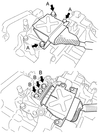 |
Check that the bolts for the generator cable are tightened to the specified torque, the generator cable is connected securely, and there are no contact problems.
Disconnect the generator cable from the hybrid transaxle assembly.
Check for arc marks at the bolts for the generator cable.
| Result | Proceed to | |
| The terminals are connected securely and there are no contact problems. | There are no arc marks. | A |
| The terminals are not connected securely and there is a contact problem. | There are arc marks. | B |
| The terminals are not connected securely and there is a contact problem. | There are no arc marks. | C |
| The terminals are connected securely and there are no contact problems. | There are arc marks. | B |
Connect the generator cable to the hybrid transaxle assembly.
Install the inverter with converter assembly.
|
| ||||
|
| ||||
| A | |
|
| 23.CHECK GENERATOR CABLE |
Check that the service plug grip is not installed.
Remove the generator cable.
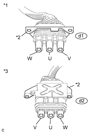 |
Using a megohmmeter set to 500 V, measure the resistance according to the value(s) in the table below.
| Tester Connection | Switch Condition | Specified Condition |
| d1-1 (W) - Body ground and shield ground | Power switch off | 100 MΩ or higher |
| d1-2 (U) - Body ground and shield ground | Power switch off | 100 MΩ or higher |
| d1-3 (V) - Body ground and shield ground | Power switch off | 100 MΩ or higher |
| *1 | Generator Cable (Inverter with Converter Assembly Side) |
| *2 | Shielded Ground |
| *3 | Generator Cable (Hybrid Vehicle Transaxle Assembly Side) |
Measure the resistance according to the value(s) in the table below.
| Tester Connection | Switch Condition | Specified Condition |
| d1-1 (W) - d2-3 (W) | Power switch off | Below 1 Ω |
| d1-2 (U) - d2-2 (U) | Power switch off | Below 1 Ω |
| d1-3 (V) - d2-1 (V) | Power switch off | Below 1 Ω |
| d1-1 (W) - d2-2 (U) | Power switch off | 100 MΩ or higher |
| d1-2 (U) - d2-1 (V) | Power switch off | 100 MΩ or higher |
| d1-3 (V) - d2-3 (W) | Power switch off | 100 MΩ or higher |
Install the generator cable.
|
| ||||
| OK | ||
| ||
| ||
| 24.CHECK HYBRID VEHICLE TRANSAXLE ASSEMBLY (MOTOR CABLE CONNECTION CONDITION) |
Check that the service plug grip is not installed.
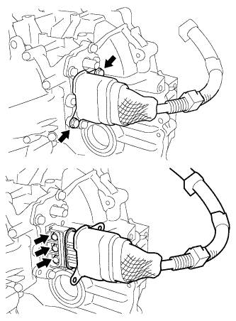 |
Check that the bolts for the motor cable are tightened to the specified torque, the motor cable is connected securely, and there are no contact problems.
Disconnect the motor cable from the hybrid transaxle assembly.
Check for arc marks at the bolts for the motor cable.
| Result | Proceed to | |
| The terminals are connected securely and there are no contact problems. | There are no arc marks. | A |
| The terminals are not connected securely and there is a contact problem. | There are arc marks. | B |
| The terminals are not connected securely and there is a contact problem. | There are no arc marks. | C |
| The terminals are connected securely and there are no contact problems. | There are arc marks. | B |
Connect the motor cable to the hybrid transaxle assembly.
|
| ||||
|
| ||||
| A | |
|
| 25.CHECK MOTOR CABLE |
Check that the service plug grip is not installed.
Remove the motor cable.
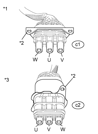 |
Using a megohmmeter set to 500 V, measure the resistance according to the value(s) in the table below.
| Tester Connection | Switch Condition | Specified Condition |
| c1-1 (W) - Body ground and shield ground | Power switch off | 100 MΩ or higher |
| c1-2 (U) - Body ground and shield ground | Power switch off | 100 MΩ or higher |
| c1-3 (V) - Body ground and shield ground | Power switch off | 100 MΩ or higher |
| *1 | Motor Cable (Inverter with Converter Assembly Side) |
| *2 | Shielded Ground |
| *3 | Motor Cable (Hybrid Vehicle Transaxle Assembly Side) |
Measure the resistance according to the value(s) in the table below.
| Tester Connection | Switch Condition | Specified Condition |
| c1-1 (W) - c2-1 (W) | Power switch off | Below 1 Ω |
| c1-2 (U) - c2-3 (U) | Power switch off | Below 1 Ω |
| c1-3 (V) - c2-2 (V) | Power switch off | Below 1 Ω |
| c1-1 (W) - c2-3 (U) | Power switch off | 100 MΩ or higher |
| c1-2 (U) - c2-2 (V) | Power switch off | 100 MΩ or higher |
| c1-3 (V) - c2-1 (W) | Power switch off | 100 MΩ or higher |
Install the motor cable.
|
| ||||
| OK | ||
| ||
| ||


