DTC P0A0D-350 High Voltage System Inter-Lock Circuit High |
DTC P0A0D-351 High Voltage System Inter-Lock Circuit High |
| DTC No. | INF Code | DTC Detection Condition | Trouble Are |
| P0A0D | 350 | Operating any of the safety devices with the vehicle stopped (ILK signal is ON) and turning the power switch on (IG) |
|
| P0A0D | 351 | Interlock signal line opens (ILK signal is ON) while the vehicle is being driven |
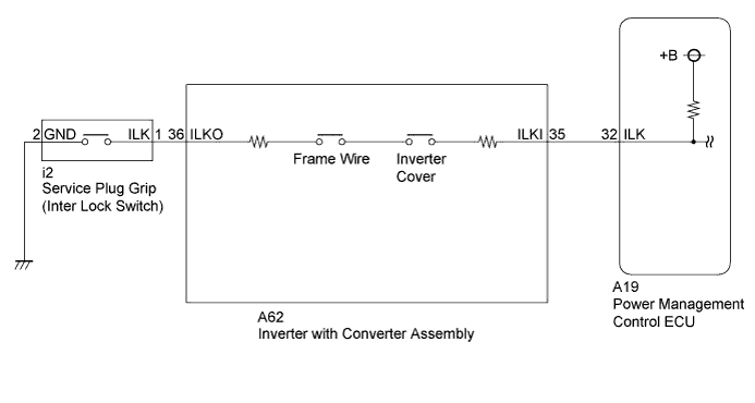
| 1.CHECK DTC OUTPUT (HYBRID CONTROL) |
Connect the intelligent tester to the DLC3.
Turn the power switch on (IG).
Enter the following menus: Powertrain / Hybrid Control / DTC.
Check if DTCs are output.
| Result | Proceed to |
| P0A0D only is output. | A |
| P0A1D is output. | B |
Turn the power switch off.
|
| ||||
| A | |
 |
| 2.CLEAR DTC |
Connect the intelligent tester to the DLC3.
Turn the power switch on (IG).
Enter the following menus: Powertrain / Hybrid Control / DTC.
Read and record the DTCs and freeze frame data.
Clear DTCs and freeze frame data.
Turn the power switch off.
| NEXT | |
|
| 3.CHECK DTC OUTPUT (HYBRID CONTROL) |
Connect the intelligent tester to the DLC3.
Turn the power switch on (IG).
Enter the following menus: Powertrain / Hybrid Control / DTC.
Check if DTCs are output.
| Result | Proceed to |
| P0A0D-350 or P0A0D-351 is output again. | A |
| Neither P0A0D-350 or P0A0D-351 is output again. | B |
Turn the power switch off.
|
| ||||
| A | |
|
| 4.CHECK SERVICE PLUG GRIP |
Check if the service plug grip is installed correctly.
|
| ||||
| OK | |
|
| 5.CHECK INVERTER COVER |
Check that the service plug grip is not installed.
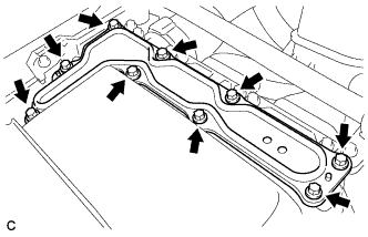 |
Check if the inverter cover of the inverter with converter assembly is installed correctly.
|
| ||||
| OK | |
|
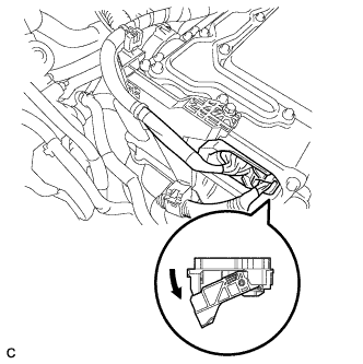
| 6.CHECK FRAME WIRE |
Check that the service plug grip is not installed.
|
Remove the inverter cover from the inverter with converter assembly.
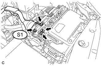 |
Check if the frame wire S1 is connected correctly.
Install the inverter cover from the inverter with converter assembly.
|
| ||||
| OK | |
|
| 7.CHECK POWER MANAGEMENT CONTROL ECU |
 |
Disconnect connector A62 from the inverter with converter assembly.
Turn the power switch on (IG).
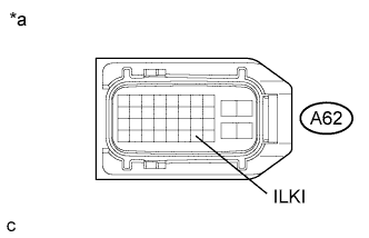 |
Measure the voltage according to the value(s) in the table below.
| Tester Connection | Switch Condition | Specified Condition |
| A62-35 (ILKI) - Body ground | Power switch on (IG) | 10 to 14 V |
| *a | Front view of wire harness connector (to Inverter with Converter Assembly) |
Turn the power switch off.
Connect the inverter with converter assembly connector.
|
| ||||
| OK | |
|
| 8.CHECK INVERTER WITH CONVERTER ASSEMBLY (INTERLOCK) |
Check that the service plug grip is not installed.
|
Disconnect connector A62 from the inverter with converter assembly.
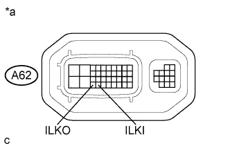 |
Measure the resistance according to the value(s) in the table below.
| Tester Connection | Switch Condition | Specified Condition |
| A62-35 (ILKI) - A62-36 (ILKO) | Power switch off | Less than 10 Ω |
| *a | Component without harness connected (Inverter with Converter Assembly) |
Connect the inverter with converter assembly connector.
|
| ||||
| OK | |
|
| 9.CHECK HARNESS AND CONNECTOR (INVERTER WITH CONVERTER ASSEMBLY - BODY GROUND) |
Install the service plug grip (Click here).
|
Disconnect connector A62 from the inverter with converter assembly.
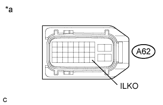 |
Measure the resistance according to the value(s) in the table below.
| Tester Connection | Switch Condition | Specified Condition |
| A62-36 (ILKO) - Body ground | Power switch off | Less than 1 Ω |
| *a | Front view of wire harness connector (to Inverter with Converter Assembly) |
Connect the inverter with converter assembly connector.
|
| ||||
| OK | |
|
| 10.CHECK CONNECTOR CONNECTION CONDITION (INTERLOCK CIRCUIT) |
Check the connections of each connector.
|
| ||||
| OK | ||
 | ||
| ||
| 11.CHECK SERVICE PLUG GRIP |
Remove the service plug grip (Click here).
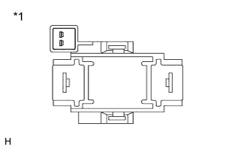 |
Check the condition of the service plug grip interlock.
| *1 | Service Plug Grip |
Install the service plug grip (Click here).
|
| ||||
| OK | |
|
| 12.CHECK HARNESS AND CONNECTOR |
Check that the service plug grip is not installed.
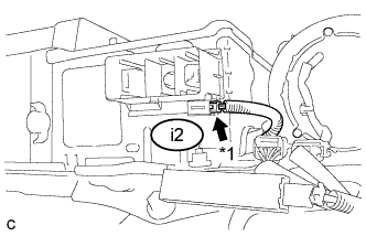 |
Check that the interlock connector at the service plug grip installation socket is connected correctly.
| *1 | Inter Lock Connector |
|
| ||||
| OK | |
|
| 13.CHECK HARNESS AND CONNECTOR (INVERTER WITH CONVERTER ASSEMBLY - SERVICE PLUG GRIP) |
Check that the service plug grip is not installed.
|
Disconnect connector A62 from the inverter with converter assembly.
Disconnect connector i2.
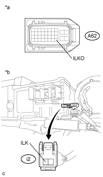 |
Measure the resistance according to the value(s) in the table below.
| Tester Connection | Switch Condition | Specified Condition |
| A62-36 (ILKO) - i2-1 (ILK) | Power switch off | Below 1 Ω |
| *a | Front view of wire harness connector (to Inverter with Converter Assembly) |
| *b | Front view of wire harness connector (to Service Plug Grip) |
Connect the service plug grip connector.
Connect the inverter with converter assembly connector.
|
| ||||
| OK | ||
| ||
| ||
| 14.CHECK INVERTER COVER |
Check that the service plug grip is not installed.
|
Remove the inverter cover from the inverter with converter assembly.
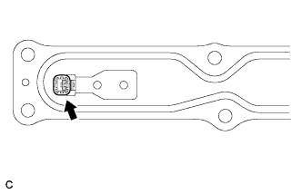 |
Check the condition of the inverter cover interlock.
Install the inverter cover from the inverter with converter assembly.
|
| ||||
| OK | |
|
| 15.CHECK FRAME WIRE (FRAME WIRE CONNECTOR) |
Check that the service plug grip is not installed.
|
Remove the inverter cover from the inverter with converter assembly.
|
Disconnect the frame wire S1 from the inverter with converter assembly.
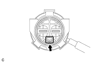 |
Check the frame wire interlock.
Connect the frame wire to the inverter with converter assembly.
Install the inverter cover from the inverter with converter assembly.
|
| ||||
| OK | ||
| ||
| ||
| 16.CHECK HARNESS AND CONNECTOR (POWER MANAGEMENT CONTROL ECU - INVERTER WITH CONVERTER) |
Turn the power switch off.
|
Disconnect connector A62 from the inverter with converter assembly.
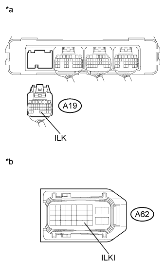 |
Disconnect connector A19 from the power management control ECU.
Measure the resistance according to the value(s) in the table below.
| Tester Connection | Switch Condition | Specified Condition |
| A19-32 (ILK) - A62-35 (ILKI) | Power switch off | Below 1 Ω |
| *a | Rear view of wire harness connector (to Power Management Control ECU) |
| *b | Front view of wire harness connector (to Inverter with Converter Assembly) |
Connect the power management control ECU connector.
Connect the inverter with converter assembly connector.
|
| ||||
| OK | ||
| ||
| ||


