DTC P0107 Manifold Absolute Pressure / Barometric Pressure Circuit Low Input |
DTC P0108 Manifold Absolute Pressure / Barometric Pressure Circuit High Input |
| DTC No. | DTC Detecting Condition | Trouble Area |
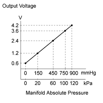
| P0107 | The output voltage from the manifold absolute pressure sensor below 0.5 V for 0.5 seconds (1 trip detection logic). |
|
| P0108 | The output voltage from the manifold absolute pressure sensor higher than 4.5 V for 0.5 seconds (1 trip detection logic). |
|
| Manifold Absolute Pressure (kPa) | Malfunction |
| Approximately 0 kPa |
|
| 130 kPa or higher |
|
| Frequency of Operation | Continuous |

| 1.READ VALUE USING INTELLIGENT TESTER (MAP) |
Connect the intelligent tester to the DLC3.
Turn the power switch on (IG).
Turn the tester on.
Enter the following menus: Powertrain / Engine and ECT / Data List / MAP.
Read the MAP value.
|
| ||||
| OK | ||
 | ||
| ||
| 2.CHECK TERMINAL VOLTAGE (MANIFOLD ABSOLUTE PRESSURE SENSOR) |
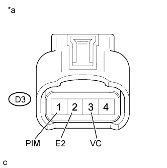 |
Disconnect the manifold absolute pressure sensor connector.
Turn the power switch on (IG).
Measure the voltage according to the value(s) in the table below.
| Tester Connection | Switch Condition | Specified Condition |
| D3-3 (VC) - D3-2 (E2) | Power switch on (IG) | 4.5 to 5.5 V |
| D3-1 (PIM) - D3-2 (E2) | Power switch on (IG) | 3.0 to 5.0 V |
| *a | Front view of wire harness connector (to Manifold Absolute Pressure Sensor) |
| Result | Proceed to |
| Outside standard range | A |
| Within standard range | B |
|
| ||||
| A | |
 |
| 3.CHECK HARNESS AND CONNECTOR (MANIFOLD ABSOLUTE PRESSURE SENSOR - ECM) |
Disconnect the manifold absolute pressure sensor connector.
Disconnect the ECM connector.
Measure the resistance according to the value(s) in the table below.
| Tester Connection | Condition | Specified Condition |
| D3-3 (VC) - D27-72 (VCPM) | Always | Below 1 Ω |
| D3-2 (E2) - D27-71 (EPIM) | Always | Below 1 Ω |
| D3-1 (PIM) - D27-69 (PIM) | Always | Below 1 Ω |
| D3-3 (VC) or D27-72 (VCPM) - Body ground | Always | 10 kΩ or higher |
| D3-1 (PIM) or D27-69 (PIM) - Body ground | Always | 10 kΩ or higher |
|
| ||||
| OK | ||
| ||
| ||
| 4.REPLACE MANIFOLD ABSOLUTE PRESSURE SENSOR |
Replace the manifold absolute pressure sensor (Click here).
| NEXT | |
|
| 5.CHECK WHETHER DTC OUTPUT RECURS (P0107 OR P0108) |
Connect the intelligent tester to the DLC3.
Turn the power switch on (IG) and turn the tester on.
Clear the DTCs.
Drive the vehicle in accordance with the driving pattern described in the Confirmation Driving Pattern.
Enter the following menus: Powertrain / Engine and ECT / DTC.
Read the DTCs.
| Result | Proceed to |
| DTC is not output | A |
| DTC P0107 or P0108 is output | B |
|
| ||||
| A | ||
| ||
| ||


