FRONT BRAKE > INSTALLATION |
| 1. INSTALL FRONT DISC |
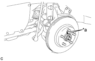 |
Align the matchmarks of the disc and axle hub, and install the disc.
| *a | Matchmark |
| 2. INSTALL FRONT DISC BRAKE CYLINDER MOUNTING |
Install the front disc brake cylinder mounting to the steering knuckle with the 2 bolts.
| 3. INSTALL FRONT DISC BRAKE BUSHING DUST BOOT |
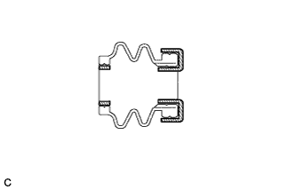 |
Apply a light layer of lithium soap base glycol grease to the entire circumference of 2 new front disc brake bushing dust boots.
 | Lithium Soap Base Glycol Grease |
Install the 2 front disc brake bushing dust boots to the front disc brake cylinder mounting.
| 4. INSTALL FRONT NO. 2 DISC BRAKE CYLINDER SLIDE PIN |
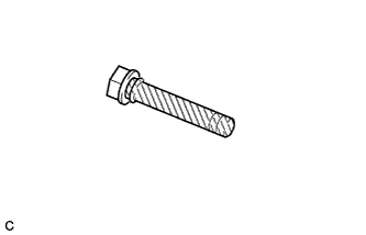 |
Apply a light layer of lithium soap base glycol grease to the sliding part and the seal surface of the front No. 2 disc brake cylinder slide pin.
| Lithium Soap Base Glycol Grease |
Install the front No. 2 disc brake cylinder slide pin to the front disc brake cylinder mounting.
Push the front No. 2 disc brake cylinder slide pin into the front disc brake bushing dust boot to align them.
| 5. INSTALL FRONT NO. 1 DISC BRAKE CYLINDER SLIDE PIN |
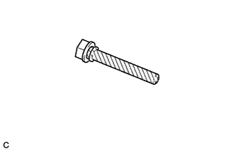 |
Apply a light layer of lithium soap base glycol grease to the sliding part and the seal surface of the front No. 1 disc brake cylinder slide pin.
| Lithium Soap Base Glycol Grease |
Install the front No. 1 disc brake cylinder slide pin to the front disc brake cylinder mounting.
Push the front No. 1 disc brake cylinder slide pin into the front disc brake bushing dust boot to align them.
| 6. INSTALL FRONT DISC BRAKE PAD SUPPORT PLATE |
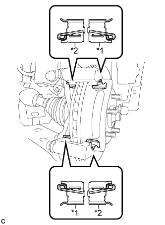 |
Install the 2 front No. 1 disc brake pad support plates and 2 front No. 2 disc brake pad support plates to the front disc brake cylinder mounting.
| *1 | Front No. 1 Disc Brake Pad Support Plate |
| *2 | Front No. 2 Disc Brake Pad Support Plate |
| 7. INSTALL FRONT ANTI-SQUEAL SHIM |
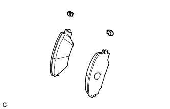 |
Install the pad wear indicator plate to each front disc brake pad.
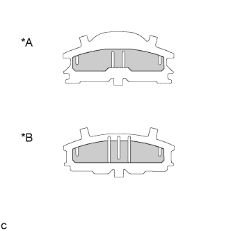 |
Apply disc brake grease to both sides of each front No. 1 anti-squeal shim as shown in the illustration.
| *A | Inner |
| *B | Outer |
 | Disc Brake Grease |
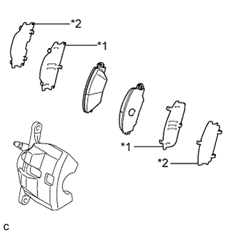 |
Install the front No. 1 anti-squeal shim and front No. 2 anti-squeal shim to each front disc brake pad.
| *1 | Front No. 1 Anti-squeal Shim |
| *2 | Front No. 2 Anti-squeal Shim |
| 8. INSTALL FRONT DISC BRAKE PAD |
Install the 2 front disc brake pads to the front disc brake cylinder mounting.
| 9. INSTALL DISC BRAKE CYLINDER ASSEMBLY |
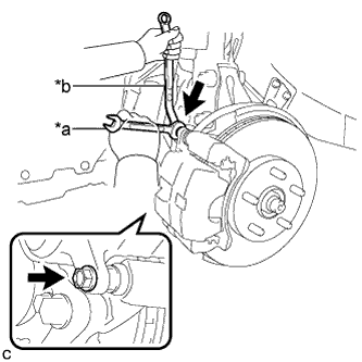 |
Hold the front disc brake cylinder slide pin, and install the disc brake cylinder assembly to the front disc brake cylinder mounting with the 2 bolts.
| *a | Hold |
| *b | Turn |
| 10. CONNECT FRONT FLEXIBLE HOSE |
Connect the front flexible hose to the disc brake cylinder assembly with a new union bolt and a new gasket.
| 11. FILL RESERVOIR WITH BRAKE FLUID |
| 12. CONNECT CABLE TO NEGATIVE AUXILIARY BATTERY TERMINAL |
Connect the cable to the negative (-) auxiliary battery terminal (Click here).
Perform the following procedure if air bleeding is not necessary:
Connect the reservoir level switch connector.
Clear the DTCs (Click here).
| 13. BLEED BRAKE LINE |
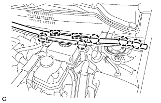 |
Disengage the 5 claws and 2 guides to remove the center cowl top ventilator louver.
Bleed brake line.
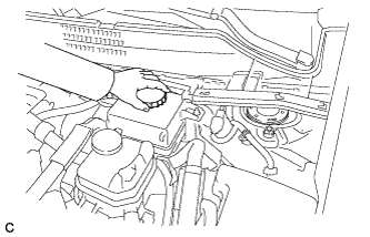 |
Remove the brake master cylinder reservoir filler cap assembly.
Add brake fluid into the reservoir between MAX and MIN level on the brake fluid reservoir.
Connect the intelligent tester to the DLC3 and turn the power switch on (IG).
Turn the intelligent tester on and enter the following menus: Chassis / ABS/VSC/TRC / Air Bleeding.
Select "Usual air bleeding" on the intelligent tester display, and bleed air from the brake fluid following the instructions on the intelligent tester.
After air bleeding, tighten each bleeder plug.
Clear the DTCs (Click here).
Turn the intelligent tester off and turn the power switch off.
Inspect for brake fluid leaks.
Install the brake master cylinder reservoir filler cap.
|
Engage the 5 claws and 2 guides to install the center cowl top ventilator louver.
| 14. INSTALL FRONT WHEEL |
