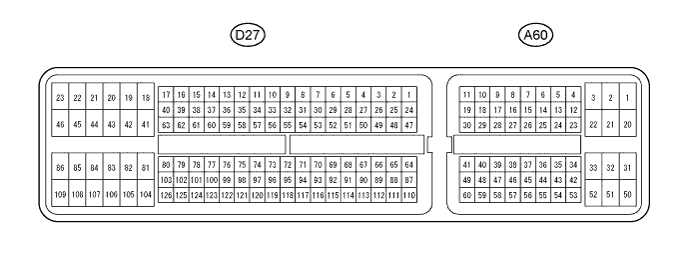
Terminal No. (Symbol)
| Wiring Color
| Terminal Description
| Condition
| Specified Condition
|
A60-20 (BATT) - D27-104 (E1)
| R - BR
| Auxiliary battery (for measuring auxiliary battery voltage and for ECM memory)
| Always
| 11 to 14 V
|
A60-2 (+B) - D27-104 (E1)
| B - BR
| Power source of ECM
| Power switch on (IG)
| 11 to 14 V
|
A60-1 (+B2) - D27-104 (E1)
| B - BR
| Power source of ECM
| Power switch on (IG)
| 11 to 14 V
|
A60-3 (+BM) - D27-104 (E1)
| GR - BR
| Power source of throttle actuator
| Always
| 11 to 14 V
|
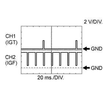
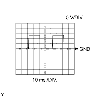
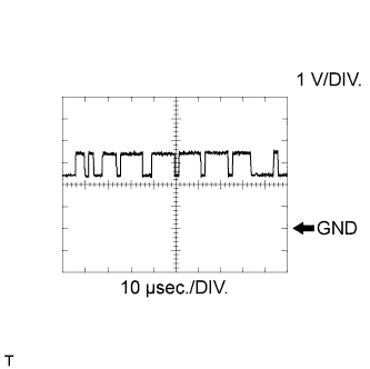
D27-108 (IGT1) - D27-104 (E1)
| GR - BR
| Ignition coil assembly
(ignition signal)
| Idling
| Pulse generation
(see waveform 1)
|
D27-107 (IGT2) - D27-104 (E1)
| W - BR
|
D27-106 (IGT3) - D27-104 (E1)
| G - BR
|
D27-105 (IGT4) - D27-104 (E1)
| Y - BR
|
D27-23 (IGF1) - D27-104 (E1)
| L - BR
| Ignition coil assembly
(ignition confirmation signal)
| Power switch on (IG)
| 4.5 to 5.5 V
|
Idling
| Pulse generation
(see waveform 1)
|
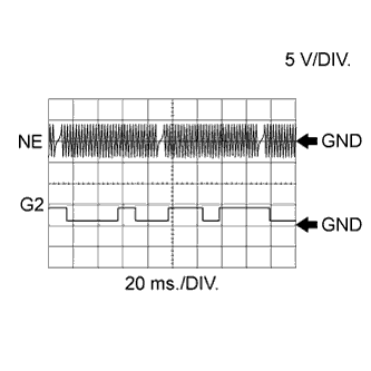
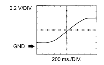
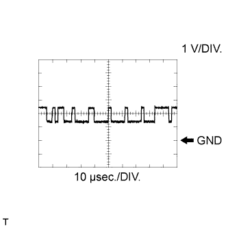
D27-74 (NE+) - D27-120 (NE-)
| B - W
| Crankshaft position sensor
| Idling with warm engine
| Pulse generation
(see waveform 2)
|
D27-76 (G2+) - D27-122 (G2-)
| B - W
| Camshaft position sensor
| Idling with warm engine
| Pulse generation
(see waveform 2)
|
D27-85 (#10) - D27-109 (E01)
| Y - BR
| Fuel injector assembly
| Power switch on (IG)
| 11 to 14 V
|
D27-84 (#20) - D27-109 (E01)
| B - BR
|
D27-83 (#30) - D27-109 (E01)
| L - BR
|
D27-82 (#40) - D27-109 (E01)
| R - BR
|
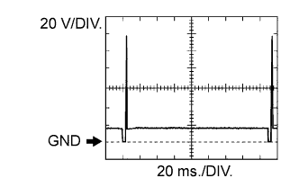
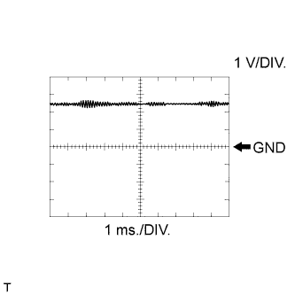
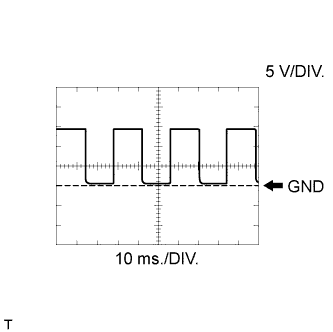
D27-85 (#10) - D27-109 (E01)
| Y - BR
| Fuel injector assembly
| Idling
| Pulse generation
(see waveform 3)
|
D27-84 (#20) - D27-109 (E01)
| B - BR
|
D27-83 (#30) - D27-109 (E01)
| L - BR
|
D27-82 (#40) - D27-109 (E01)
| R - BR
|
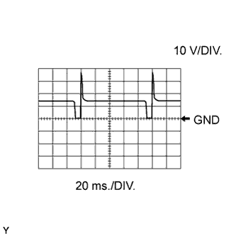
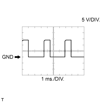
D27-18 (HA1A) - D27-46 (E04)
| Y - BR
| Air fuel ratio sensor (sensor 1) heater
| Power switch on (IG)
| 11 to 14 V
|
Idling with warm engine
| Pulse generation
(see waveform 4)
|
D27-103 (A1A+) - D27-104 (E1)
| Y - BR
| Air fuel ratio sensor (sensor 1)
| Idling
| 3.3 V*1
|
D27-126 (A1A-) - D27-104 (E1)
| BR - BR
| Air fuel ratio sensor (sensor 1)
| Idling
| 3.0 V*1
|
D27-41 (HT1B) - D27-86 (E03)
| BR - BR
| Heated oxygen sensor (sensor 2) heater
| Power switch on (IG)
| 11 to 14 V
|
Idling
| Below 3.0 V
|
D27-125 (OX1B) - D27-102 (O1B-)
| L - P
| Heated oxygen sensor (sensor 2)
| Engine speed maintained at 2500 rpm for 2 minutes after warming up engine
| Pulse generation
(see waveform 5)
|
D27-87 (KNK1) - D27-110 (EKNK)
| B - W
| Knock control sensor
| Engine speed maintained at 2500 rpm after warming up engine
| Pulse generation
(see waveform 6)
|
D27-64 (THW) - D27-65 (ETHW)
| P - BR
| Engine coolant temperature sensor
| Idling, Engine coolant temperature 80°C (176°F)
| 0.2 to 1.0 V
|
D27-116 (THA) - D27-93 (ETHA)
| P - BR
| Intake air temperature sensor (built into mass air flow meter sub-assembly)
| Idling, Intake air temperature 20°C (68°F)
| 0.5 to 3.4 V
|
D27-94 (VG) - D27-117 (E2G)
| B - W
| Mass air flow meter sub-assembly
| Idling, shift lever in N, A/C switch OFF
| 0.5 to 3.0 V
|
A60-36 (W) - D27-104 (E1)
| LG - BR
| MIL
| Power switch on (IG) (MIL goes on)
| Below 3.0 V
|
Idling
| 11 to 14 V
|
D27-90 (VTA1) - D27-111 (ETA)
| Y - G
| Throttle position sensor (for engine control)
| Accelerator pedal released
(Throttle valve fully closed)
| 0.5 to 1.1 V
|
D27-89 (VTA2) - D27-111 (ETA)
| B - G
| Throttle position sensor (for sensor malfunction detection)
| Accelerator pedal released
(Throttle valve fully closed)
| 2.1 to 3.1 V
|
D27-88 (VCTA) - D27-111 (ETA)
| R - G
| Power source of throttle position sensor (specific voltage)
| Power switch on (IG)
| 4.5 to 5.5 V
|
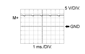
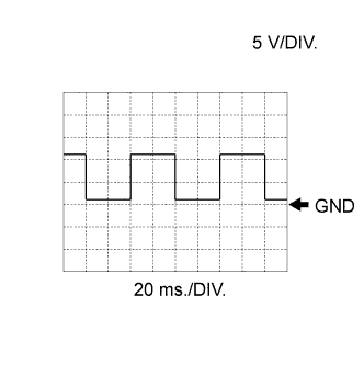
D27-21 (M+) - D27-19 (ME01)
| L - BR
| Throttle actuator
| Idling with warm engine
| Pulse generation
(see waveform 7)
|
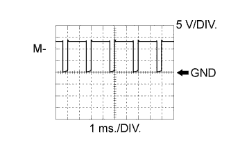
D27-20 (M-) - D27-19 (ME01)
| P - BR
| Throttle actuator
| Idling with warm engine
| Pulse generation
(see waveform 8)
|
D27-28 (PRG) - D27-104 (E1)
| V - BR
| Purge VSV
| Power switch on (IG)
| 11 to 14 V
|
Idling, under purge control
| Pulse generation
(see waveform 9)
|
A60-8 (FC) - D27-104 (E1)
| R - BR
| Fuel pump control
| Power switch on (IG)
| 11 to 14 V
|
Idling
| Below 1.5 V
|
A60-7 (TC) - D27-104 (E1)
| P - BR
| Terminal TC of DLC3
| Power switch on (IG)
| 11 to 14 V
|
A60-26 (TACH) - D27-104 (E1)
| B - BR
| Engine speed
| Idling
| Pulse generation
(see waveform 10)
|
D27-36 (OC1+) - D27-59 (OC1-)
| Y - G
| Camshaft timing oil control valve assembly
| Idling
| Pulse generation
(see waveform 11)
|
A60-13 (CANH) - D27-104 (E1)
| P - BR
| CAN communication line
| Engine stopped and power switch on (IG)
| Pulse generation
(see waveform 12)
|
A60-5 (CANL) - D27-104 (E1)
| V - BR
| CAN communication line
| Engine stopped and power switch on (IG)
| Pulse generation
(see waveform 13)
|
A60-12 (CANP) - D27-104 (E1)
| B - BR
| CAN communication line
| Engine stopped and power switch on (IG)
| Pulse generation
(see waveform 12)
|
A60-4 (CANN) - D27-104 (E1)
| W - BR
| CAN communication line
| Engine stopped and power switch on (IG)
| Pulse generation
(see waveform 13)
|
A60-28 (IGSW) - D27-104 (E1)
| W - BR
| Power switch
| Power switch on (IG)
| 11 to 14 V
|
A60-6 (MREL) - D27-104 (E1)
| G - BR
| EFI MAIN relay
| Power switch on (IG)
| 11 to 14 V
|
D27-99 (VCV1) - D27-104 (E1)
| R - BR
| Power source of camshaft position sensor
| Power switch on (IG)
| 4.5 to 5.5 V
|
A60-10 (WPO) - D27-104 (E1)
| L - BR
| Engine water pump assembly
| Idling with warm engine
| Pulse generation
(see waveform 14)
|
A60-11 (WPI) - D27-104 (E1)
| G - BR
| Engine water pump assembly
| Idling with warm engine
| Pulse generation
(see waveform 15)
|
D27-72 (VCPM) - D27-71 (EPIM)
| L - Y
| Manifold absolute pressure sensor
| Power switch on (IG)
| 4.5 to 5.5 V
|
D27-69 (PIM) - D27-71 (EPIM)
| B - Y
| Manifold absolute pressure sensor
| Power switch on (IG)
| 3.0 to 5.0 V
|
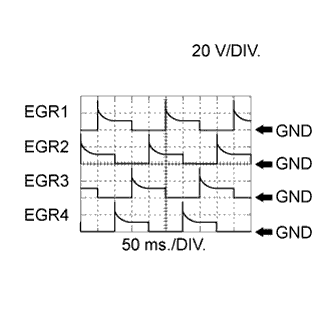
D27-45 (EGR1) - D27-104 (E1)
| R - BR
| EGR valve assembly
| Repeating quick engine speed accelerations
| Pulse generation
(see waveform 16)
|
D27-44 (EGR2) - D27-104 (E1)
| V - BR
| EGR valve assembly
| Repeating quick engine speed accelerations
| Pulse generation
(see waveform 16)
|
D27-43 (EGR3) - D27-104 (E1)
| Y - BR
| EGR valve assembly
| Repeating quick engine speed accelerations
| Pulse generation
(see waveform 16)
|
D27-42 (EGR4) - D27-104 (E1)
| LG - BR
| EGR valve assembly
| Repeating quick engine speed accelerations
| Pulse generation
(see waveform 16)
|
D27-48 (G2O) - D27-104 (E1)
| Y - BR
| Camshaft position signal
| Idling
| Pulse generation
(see waveform 17)
|
A60-22 (FANH) - D27-104 (E1)
| LG - BR
| Cooling fan relay
| Power switch on (IG)
| 11 to 14 V
|
A60-21 (FANL) - D27-104 (E1)
| L - BR
| Cooling fan relay
| Power switch on (IG)
| 11 to 14 V
|
A60-46 (PWMS) - D27-104 (E1)
| G - BR
| Combination switch assembly (mode switch)
| Power switch on (IG), mode switch being turned and held at SPORT position
| 0 to 1.5 V
|
A60-30 (NE01) - D27-104 (E1)
| L - BR
| Combination switch assembly (mode switch)
| Power switch on (IG), mode switch being pushed and held at NORMAL position
| 0 to 1.5 V
|
D27-104 (E1) - Body ground
| BR - Body ground
| Ground
| Always
| Below 1 Ω
|
D27-109 (E01) - Body ground
| BR - Body ground
| Ground
| Always
| Below 1 Ω
|
D27-81 (E02) - Body ground
| W-B - Body ground
| Ground
| Always
| Below 1 Ω
|
D27-86 (E03) - Body ground
| BR - Body ground
| Ground
| Always
| Below 1 Ω
|
D27-46 (E04) - Body ground
| BR - Body ground
| Ground
| Always
| Below 1 Ω
|
A60-32 (EC) - Body ground
| W-B - Body ground
| Ground
| Always
| Below 1 Ω
|
D27-22 (GE01) - D27-104 (E1)
| W-B - BR
| Shield earth (ground) circuit of throttle actuator
| Always
| Below 1 V
|