WIPER AND WASHER SYSTEM > Washer Fluid Level Warning Switch Circuit |
| 1.INSPECT LEVEL WARNING SWITCH ASSEMBLY |
Fill the washer jar with washer fluid.
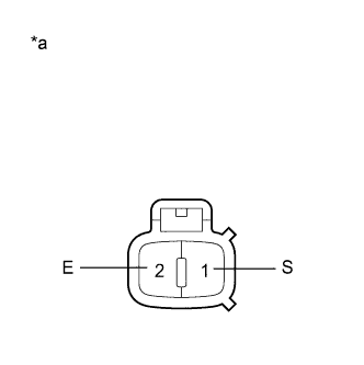 |
Measure the resistance according to the value(s) in the table below.
| Tester Connection | Condition | Specified Condition |
| 1 (S) - 2 (E) | Fluid volume is more than 800 ml | 10 kΩ or higher |
| 1 (S) - 2 (E) | Fluid volume is less than 600 ml | Below 1 Ω |
| *a | Component without harness connected (Level Warning Switch Assembly) |
|
| ||||
| OK | |
 |
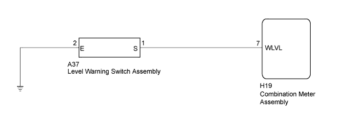
| 2.CHECK HARNESS AND CONNECTOR (LEVEL WARNING SWITCH - COMBINATION METER AND BODY GROUND) |
Disconnect the H19 combination meter assembly connector.
Measure the resistance according to the value(s) in the table below.
| Tester Connection | Condition | Specified Condition |
| H19-7 (WLVL) - A37-1 (S) | Always | Below 1 Ω |
| A37-2 (E) - Body ground | Always | Below 1 Ω |
| H19-7 (WLVL) - Body ground | Always | 10 kΩ or higher |
|
| ||||
| OK | ||
 | ||
| ||

