LIGHTING SYSTEM > TERMINALS OF ECU |
| CHECK INSTRUMENT PANEL JUNCTION BLOCK ASSEMBLY AND MAIN BODY ECU (MULTIPLEX NETWORK BODY ECU) |
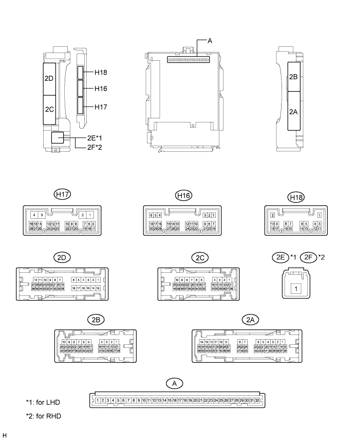
Disconnect the instrument panel junction block assembly and main body ECU (multiplex network body ECU) connectors.
Measure the voltage according to the value(s) in the table below.
| Terminal No. (Symbol) | Wiring Color | Terminal Description | Condition | Specified Condition |
| 2B-25 - Body ground | B - Body ground | IG power supply | Power switch on (IG) | 11 to 14 V |
| Power switch off | Below 1 V | |||
| 2C-18 (BECU) - Body ground | B - Body ground | Auxiliary battery power supply | Power switch off | 11 to 14 V |
| 2E-1*1 - Body ground 2F-1*2 - Body ground | W - Body ground | Auxiliary battery power supply | Power switch off | 11 to 14 V |
Measure the resistance according to the value(s) in the table below.
| Terminal No. (Symbol) | Wiring Color | Terminal Description | Condition | Specified Condition |
| 2B-6 (GND1) - Body ground | W-B - Body ground | Ground | Always | Below 1 Ω |
| H17-3 (GND2) - Body ground | W-B - Body ground | Ground | Always | Below 1 Ω |
Reconnect the instrument panel junction block assembly and main body ECU (multiplex network body ECU) connectors.
Measure the voltage and check for pulses according to the value(s) in the table below.
| Terminal No. (Symbol) | Wiring Color | Terminal Description | Condition | Specified Condition |
| 2C-20 (PKB) - Body ground | R - Body ground | Parking brake switch input | Parking brake switch on | Below 1 V |
| Parking brake switch off | 11 to 14 V | |||
| 2C-32 (HRLY) - Body ground | G - Body ground | Headlight relay drive output | Light control switch in head position | Below 1 V |
| Light control switch not in head position | 11 to 14 V | |||
| H16-15 (DRL)*1 - Body ground | Y - Body ground | Daytime running light system drive output | Daytime running light system operates | Below 1 V |
| Daytime running light system not operates | 11 to 14 V | |||
| H17-2 (LSWR) - Body ground | GR - Body ground | Rear door unlock detection switch RH input | Rear door RH locked | Pulse generation |
| Rear door RH unlocked | Below 1 V | |||
| 2C-22 (DIM) - Body ground | Y - Body ground | High beam headlights drive output | Dimmer switch in high or high flash position | Below 1 V |
| Dimmer switch in low position | 11 to 14 V | |||
| H16-8 (HF) - Body ground | LG - Body ground | Dimmer switch high flash position signal input | Dimmer switch in high flash position | Below 1 V |
| Dimmer switch not in high flash position | Pulse generation | |||
| H16-20 (CLTB) - Body ground | R - Body ground | Automatic light control sensor power supply output | Power switch off | Below 1 V |
| Power switch on (IG) and light control switch in AUTO position | 11 to 14 V | |||
| H16-21 (CLTS) - Body ground | W - Body ground | Automatic light control sensor signal input | Power switch off | Below 1 V |
| Automatic light control system operates | Pulse generation (See waveform 1) | |||
| H16-27 (FFOG) - Body ground | LG - Body ground | Front fog light switch input | Front fog light switch on | Below 1 V |
| Front fog light switch off | Pulse generation | |||
| H16-28 (A) - Body ground | W - Body ground | Light control switch AUTO position signal input | Light control switch in AUTO position | Below 1 V |
| Light control switch not in AUTO position | Pulse generation | |||
| H16-29 (HEAD) - Body ground | L - Body ground | Light control switch head position input | Light control switch in head position | Below 1 V |
| Light control switch not in head position and power switch off | Pulse generation | |||
| Light control switch not in head position and power switch on (IG) | 11 to 14 V | |||
| H16-30 (TAIL) - Body ground | Y - Body ground | Light control switch tail position signal input | Light control switch in tail or head position | Below 1 V |
| Light control switch in neither tail nor head position, and power switch off | Pulse generation | |||
| Light control switch in neither tail nor head position, and power switch on (IG) | 11 to 14 V |
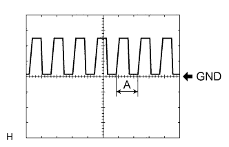 |
Waveform 1
| Item | Content |
| Tool setting | 5 V/DIV., 5 ms./DIV. |
| CHECK POWER MANAGEMENT CONTROL ECU |
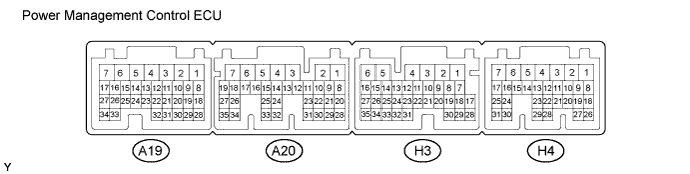
Measure the voltage according to the value(s) in the table below.
| Terminal No. (Symbol) | Wiring Color | Terminal Description | Condition | Specified Condition |
| A19-15 (BL) - H3-6 (E1) | LG - W-B | Back up light | Power switch on (IG), reverse (R) selected | 11 to 14 V |
| CHECK HEADLIGHT LEVELING ECU ASSEMBLY |
Disconnect the A46 headlight leveling ECU assembly connector.
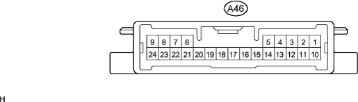
Measure the voltage and resistance according to the value(s) in the table below.
| Terminal No. (Symbol) | Wiring Color | Terminal Description | Condition | Specified Condition |
| A46-1 (IG) - Body ground | LG - Body ground | IG power supply | Power switch off | Below 1 V |
| Power switch on (IG) | 11 to 14 V |
| Terminal No. (Symbol) | Wiring Color | Terminal Description | Condition | Specified Condition |
| A46-9 (E1) - Body ground | W-B - Body ground | Ground | Always | Below 1 Ω |
Reconnect the A46 headlight leveling ECU assembly connector.
Measure the resistance and voltage according to the value(s) in the table below.
| Terminal No. (Symbol) | Wiring Color | Terminal Description | Condition | Specified Condition |
| A46-21 (SGR) - Body ground | Y - Body ground | Rear height control sensor ground | Always | Below 1 Ω |
| A46-23 (RH-) - Body ground | BR - Body ground | Leveling motor RH ground | Always | Below 1 Ω |
| A46-24 (LH-) - Body ground | LG - Body ground | Leveling motor LH ground | Always | Below 1 Ω |
| Terminal No. (Symbol) | Wiring Color | Terminal Description | Condition | Specified Condition |
| A46-3 (HDLP) - Body ground | V - Body ground | Low beam headlight signal input | Low beam headlights on | Below 1.5 V |
| Low beam headlights off | Above 5 V | |||
| A46-5 (INIT) - Body ground | B - Body ground | Initialization signal input | Terminals LVL and GND of DLC3 connected | Below 1 V |
| Terminals LVL and GND of DLC3 not connected | Approx. 5 V | |||
| A46-6 (WNG) - Body ground | L - Body ground | Warning indicator drive output | Warning indicator on | Below 1 V |
| Warning indicator off | 11 to 14 V | |||
| A46-10 (RH+) - Body ground | W - Body ground | Leveling motor RH power supply | Power switch off | Below 1 V |
| Power switch on (IG) | 11 to 14 V | |||
| A46-11 (LH+) - Body ground | R - Body ground | Leveling motor LH power supply | Power switch off | Below 1 V |
| Power switch on (IG) | 11 to 14 V | |||
| A46-12 (SBR) - Body ground | P - Body ground | Rear height control sensor power supply | Power switch off | Below 1 V |
| Power switch on (IG) | 4.75 to 5.25 V | |||
| A46-16 (SPDR) - Body ground | V - Body ground | Vehicle speed signal input | Vehicle is driven at approx. 20 km/h (12mph) | Pulse generation (See waveform 1) |
| A46-17 (RHT) - Body ground | B - Body ground | Leveling motor RH operation signal input | With low beam headlights on, vehicle height not changed | Below 1 V |
| With low beam headlights on, change vehicle height and keep for more than 3 seconds | 1.0 to 14.4 V | |||
| A46-18 (LHT) - Body ground | G - Body ground | Leveling motor LH operation signal input | With low beam headlights on, vehicle height not changed | Below 1 V |
| With low beam headlights on, change vehicle height and keep for more than 3 seconds | 1.0 to 14.4 V | |||
| A46-19 (SHRL) - Body ground | SB - Body ground | Rear height control sensor signal input | Power switch off | Below 1 V |
| Power switch on (IG) | 0.5 to 4.5 V |
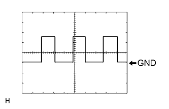 |
Waveform 1
| Item | Content |
| Tool setting | 5 V/DIV., 20 ms./DIV. |
| Vehicle condition | Driving at approx. 20 km/h (12 mph) |
| CHECK OUTER MIRROR CONTROL ECU ASSEMBLY (LH SIDE) |

Disconnect the K7 connector.
Measure the voltage according to the value(s) in the table below.
| Tester Connection | Wiring Color | Terminal Description | Condition | Specified Condition |
| K7-14 (BDR) - Body ground | L - Body ground | +B power supply | Power switch off | 11 to 14 V |
| K7-6 (CPUB) - Body ground | LG - Body ground | +B power supply | Power switch off | 11 to 14 V |
| K7-5 (SIG) - Body ground | Y - Body ground | Ignition power supply | Power switch off → on (IG) | 0 V → 11 to 14 V |
Measure the resistance according to the value(s) in the table below.
| Tester Connection | Wiring Color | Terminal Description | Condition | Specified Condition |
| K7-7 (GND) - Body ground | W-B - Body ground | Ground | Always | Below 1 Ω |
Reconnect the K7 connector.
Measure the voltage according to the value(s) in the table below.
| Tester Connection | Wiring Color | Terminal Description | Condition | Specified Condition |
| z6-1 (LMVR) - z6-9 (LMHR) | W - R | Vertical mirror motor drive voltage | LH mirror surface moving upward → stopped | 11 to 14 V → 0 V |
| CHECK OUTER MIRROR CONTROL ECU ASSEMBLY (RH SIDE) |

Disconnect the J8 connector.
Measure the voltage according to the value(s) in the table below.
| Tester Connection | Wiring Color | Terminal Description | Condition | Specified Condition |
| J8-6 (CPUB) - Body ground | LG - Body ground | +B power supply | Power switch off | 11 to 14 V |
| J8-14 (BDR) - Body ground | L - Body ground | +B power supply | Power switch off | 11 to 14 V |
| J8-5 (SIG) - Body ground | Y - Body ground | Ignition power supply | Power switch off → on (IG) | 0 V → 11 to 14 V |
Measure the resistance according to the value(s) in the table below.
| Tester Connection | Wiring Color | Terminal Description | Condition | Specified Condition |
| J8-7 (GND) - Body ground | W-B - Body ground | Ground | Always | Below 1 Ω |
Reconnect the J8 connector.
Measure the voltage according to the value(s) in the table below.
| Tester Connection | Wiring Color | Terminal Description | Condition | Specified Condition |
| z7-1 (RMVR) - z7-9 (RMHR) | W - R | Vertical mirror motor drive voltage | RH mirror surface moving upward → stopped | 11 to 14 V → 0 V |
