NAVIGATION SYSTEM (for HDD) > Display does not Dim when Light Control Switch is Turned ON |
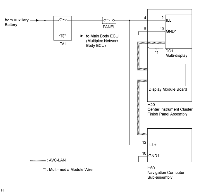
| 1.CONFIRM SYMPTOMS |
Check the symptoms that occur by viewing the display.
| Result | Proceed to |
| There is a delay until the display dims after the navigation system is activated with the light control switch in the tail or head position. | A |
| The display dims for a moment and then becomes bright after the navigation system is activated with the light control switch in the tail or head position. | B |
| When the light control switch is set to the tail or head position, the display dims but does not switch to the night screen. | B |
| When the light control switch is set to the tail or head position, the display neither dims nor switches to the night screen. | C |
|
| ||||
|
| ||||
| A | |
 |
| 2.CHECK HARNESS AND CONNECTOR (ILLUMINATION SIGNAL) |
Disconnect the H20 multi-media module wire connector.
Measure the resistance according to the value(s) in the table below.
| Tester Connection | Condition | Specified Condition |
| H20-6 (GND1) - Body ground | Always | Below 1 Ω |
Measure the voltage according to the value(s) in the table below.
| Tester Connection | Condition | Specified Condition |
| H20-4 (ILL) - H20-6 (GND1) | Light control switch in the tail or head position | 11 to 14 V |
|
| ||||
| OK | |
|
| 3.INSPECT MULTI-MEDIA MODULE WIRE |
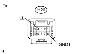 |
Disconnect the H20 multi-media module wire connector.
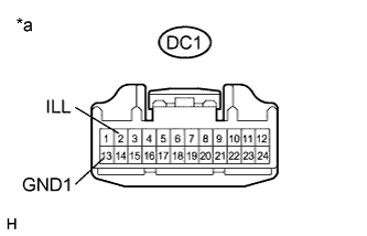 |
Disconnect the DC1 multi-media module wire connector.
Measure the resistance according to the value(s) in the table below.
| Tester Connection | Condition | Specified Condition |
| H20-4 (ILL) - DC1-2 (ILL) | Always | Below 1 Ω |
| H20-6 (GND1) - DC1-13 (GND1) | Always | Below 1 Ω |
| *a | Component without harness connected (Multi-media Module Wire) |
|
| ||||
| OK | ||
 | ||
| ||
| 4.CHECK IMAGE QUALITY SETTING |
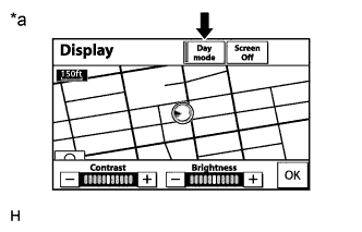 |
Press the "DISP" switch on the remote touch.
Turn the light control switch to the tail position.
Check if "Day mode" on the display adjustment screen is on.
| Result | Proceed to |
| "Day mode" is on | A |
| "Day mode" is off | B |
| *a | Example |
|
| ||||
| A | ||
| ||
| ||
| 5.CHECK VEHICLE SIGNAL (ILLUMINATION SIGNAL) |
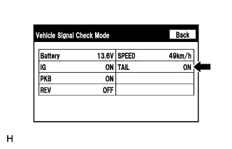 |
Enter the "Vehicle Signal Check Mode" screen. Refer to Check Vehicle Signal in Operation Check (Click here).
Check that the display changes between ON and OFF according to the light control switch operation.
| Light Control Switch | Display |
| Tail or head | ON |
| Off | OFF |
|
| ||||
| OK | ||
| ||
| ||
| 6.CHECK HARNESS AND CONNECTOR (ILLUMINATION SIGNAL) |
Disconnect the H60 navigation computer sub-assembly connector.
Measure the resistance according to the value(s) in the table below.
| Tester Connection | Condition | Specified Condition |
| H60-10 (GND1) - Body ground | Always | Below 1 Ω |
Measure the voltage according to the value(s) in the table below.
| Tester Connection | Condition | Specified Condition |
| H60-12 (ILL+) - H60-10 (GND1) | Light control switch in the tail or head position | 11 to 14 V |
|
| ||||
| OK | ||
| ||
| ||


