ENGINE IMMOBILISER SYSTEM > TERMINALS OF ECU |
| CHECK POWER SWITCH |

Measure the resistance and voltage according to the value(s) in the table below.
| Terminal No. (Symbol) | Input/Output | Wiring Color | Terminal Description | Condition | Specified Condition | Related Data List Item/DTC |
| H78-8 (AGND) - Body ground | - | P - Body ground | Ground | Always | Below 1 Ω | - |
| H78-9 (TXCT) - H78-8 (AGND) | Input | V - P | Immobiliser communication input | Power switch off, brake pedal not depressed, 30 seconds or more after driver door opened and then closed | Below 1 V | - |
| H78-10 (CODE) - H78-8 (AGND) | Output | L - P | Immobiliser communication output | Power switch off, brake pedal not depressed, 30 seconds or more after driver door opened and then closed | Below 1 V | - |
| H78-14 (VC5) - H78-8 (AGND) | Input | Y - P | Transponder key amplifier power supply | Power switch off, brake pedal not depressed, 30 seconds or more after driver door opened and then closed | Below 1 V | - |
| Terminal No. (Symbol) | Input/Output | Wiring Color | Terminal Description | Condition | Specified Condition | Related Data List Item/DTC |
| H78-9 (TXCT) - H78-8 (AGND) | Input | V - P | Signal input from certification ECU (smart key ECU assembly) (Code sent from certification ECU (smart key ECU assembly) to transponder key amplifier built into power switch, and then transmitted by antenna of transponder key amplifier as electric waves) | After power switch turned off, within 30 seconds of any door opened and closed, or brake pedal depressed | Pulse generation (See waveform 1) |
|
| H78-10 (CODE) - H78-8 (AGND) | Output | L - P | Signal output to certification ECU (smart key ECU assembly) (Electric waves from transponder key amplifier built into power switch used to detect key information. Information then sent to certification ECU (smart key ECU assembly)) | After power switch turned off, within 30 seconds of any door opened and closed, or brake pedal depressed, and then key held against power switch* | Pulse generation (See waveform 2) | |
| H78-14 (VC5) - H78-8 (AGND) | Input | Y - P | Transponder key amplifier power supply (Power supplied from certification ECU (smart key ECU assembly) when transponder key amplifier built into power switch activated) | After power switch turned off, within 30 seconds of any door opened and closed, or brake pedal depressed | Pulse generation (See waveform 3) |
Inspect using an oscilloscope.
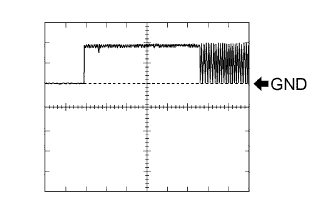 |
Waveform 1 (Reference)
| Item | Content |
| Tester Connection | H78-9 (TXCT) - H78-8 (AGND) |
| Tool Setting | 2 V/DIV., 20 ms./DIV. |
| Condition | After power switch turned off, within 30 seconds of any door opened and closed, or brake pedal depressed |
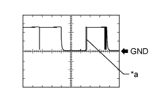 |
Waveform 2 (Reference)
| *a | Key held against power switch |
| Item | Content |
| Tester Connection | H78-10 (CODE) - H78-8 (AGND) |
| Tool Setting | 1 V/DIV., 200 ms./DIV. |
| Condition | After power switch turned off, within 30 seconds of any door opened and closed, or brake pedal depressed, and then key held against power switch* |
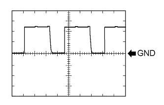 |
Waveform 3 (Reference)
| Item | Content |
| Tester Connection | H78-14 (VC5) - H78-8 (AGND) |
| Tool Setting | 2 V/DIV., 200 ms./DIV. |
| Condition | After power switch turned off, within 30 seconds of any door opened and closed, or brake pedal depressed |
| CHECK CERTIFICATION ECU (SMART KEY ECU ASSEMBLY) |
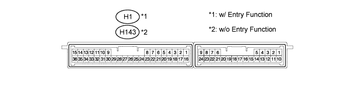
Disconnect the H1*1 or H143*2 ECU connector.
Measure the resistance and voltage according to the value(s) in the table below.
| Terminal No. (Symbol) | Input/Output | Wiring Color | Terminal Description | Condition | Specified Condition | Related Data List Item/DTC |
| H1-1 (+B) - H1-15 (E)*1 H143-1 (+B) - H143-15 (E)*2 | Input | B - W-B | +B power supply | Power switch off | 11 to 14 V | - |
| H1-17 (CUTB) - H1-15 (E)*1 H143-17 (CUTB) - H143-15 (E)*2 | Input | Y - W-B | Dark current cut pin* | Power switch off | 11 to 14 V | - |
| H1-15 (E) - Body ground*1 H143-15 (E) - Body ground*2 | - | W-B - Body ground | Ground | Always | Below 1 Ω | - |
Reconnect the H1*1 or H143*2 ECU connector.
Measure the resistance and voltage according to the value(s) in the table below.
| Terminal No. (Symbol) | Input/Output | Wiring Color | Terminal Description | Condition | Specified Condition | Related Data List Item/DTC |
| H1-2 (IND) - H1-15 (E)*1 H143-2 (IND) - H143-15 (E)*2 | Output | BR - W-B | Security indicator output | Power switch off → on (IG) | Pulse generation → Below 2 V | - |
| H1-12 (TXCT) - H1-36 (AGND)*1 H143-12 (TXCT) - H143-36 (AGND)*2 | Output | V - P | Signal output to transponder key amplifier | Power switch off, brake pedal not depressed, 30 seconds or more after driver door opened and then closed | Below 1 V |
|
| H1-13 (CODE) - H1-36 (AGND)*1 H143-13 (CODE) - H143-36 (AGND)*2 | Input | L - P | Signal input from transponder key amplifier | Power switch off, brake pedal not depressed, 30 seconds or more after driver door opened and then closed | Below 1 V | |
| H1-16 (IG) - H1-15 (E)*1 H143-16 (IG) - H143-15 (E)*2 | Input | BE - W-B | Ignition power supply | Power switch off → on (IG) | Below 1 V → 11 to 14 V | Ignition Switch |
| H1-28 (VC5) - H1-36 (AGND)*1 H143-28 (VC5) - H143-36 (AGND)*2 | Output | Y - P | Transponder key amplifier power supply | Power switch off, brake pedal not depressed, 30 seconds or more after driver door opened and then closed | Below 1 V |
|
| H1-36 (AGND) - Body ground*1 H143-36 (AGND) - Body ground*2 | - | P - Body ground | Transponder key amplifier ground | Always | Below 1 Ω |
| Terminal No. (Symbol) | Input/Output | Wiring Color | Terminal Description | Condition | Specified Condition | Related Data List Item/DTC |
| H1-12 (TXCT) - H1-36 (AGND)*1 H143-12 (TXCT) - H143-36 (AGND)*2 | Output | V - P | Signal output to transponder key amplifier (Code sent from certification ECU (smart key ECU assembly) to transponder key amplifier built into power switch, and then transmitted by antenna of transponder key amplifier as electric waves) | After power switch turned off, within 30 seconds of any door opened and closed, or brake pedal depressed | Pulse generation (See waveform 1) |
|
| H1-13 (CODE) - H1-36 (AGND)*1 H143-13 (CODE) - H143-36 (AGND)*2 | Input | L - P | Signal input from transponder key amplifier (Electric waves from transponder key amplifier built into power switch used to detect key information. Information then sent to certification ECU (smart key ECU assembly)) | After power switch turned off, within 30 seconds of any door opened and closed, or brake pedal depressed, and then key held against power switch* | Pulse generation (See waveform 2) | |
| H1-28 (VC5) - H1-36 (AGND)*1 H143-28 (VC5) - H143-36 (AGND)*2 | Output | Y - P | Transponder key amplifier power supply (Power supplied from certification ECU (smart key ECU assembly) when transponder key amplifier built into power switch activated) | After power switch turned off, within 30 seconds of any door opened and closed, or brake pedal depressed | Pulse generation (See waveform 3) |
Inspect using an oscilloscope.
|
Waveform 1 (Reference)
| Item | Content |
| Tester Connection | H1-12 (TXCT) - H1-36 (AGND)*1 H143-12 (TXCT) - H143-36 (AGND)*2 |
| Tool Setting | 2 V/DIV., 20 ms./DIV. |
| Condition | After power switch turned off, within 30 seconds of any door opened and closed, or brake pedal depressed |
|
Waveform 2 (Reference)
| *a | Key held against power switch |
| Item | Content |
| Tester Connection | H1-13 (CODE) - H1-36 (AGND)*1 H143-13 (CODE) - H143-36 (AGND)*2 |
| Tool Setting | 1 V/DIV., 200 ms./DIV. |
| Condition | After power switch turned off, within 30 seconds of any door opened and closed, or brake pedal depressed, and then key held against power switch* |
|
Waveform 3 (Reference)
| Item | Content |
| Tester Connection | H1-28 (VC5) - H1-36 (AGND)*1 H143-28 (VC5) - H143-36 (AGND)*2 |
| Tool Setting | 2 V/DIV., 200 ms./DIV. |
| Condition | After power switch turned off, within 30 seconds of any door opened and closed, or brake pedal depressed |
| CHECK ID CODE BOX (IMMOBILISER CODE ECU) |

Disconnect the H22 box connector.
Measure the resistance and voltage according to the value(s) in the table below.
| Terminal No. (Symbol) | Input/Output | Wiring Color | Terminal Description | Condition | Specified Condition | Related Data List Item/DTC |
| H22-1 (+B) - H22-8 (GND) | Input | L - W-B | +B power supply | Power switch off | 11 to 14 V | B2789 |
| H22-8 (GND) - Body ground | - | W-B - Body ground | Ground | Always | Below 1 Ω | B2789 |
Reconnect the H22 box connector.
Measure the voltage according to the value(s) in the table below.
| Terminal No. (Symbol) | Input/Output | Wiring Color | Terminal Description | Condition | Specified Condition | Related Data List Item/DTC |
| H22-5 (EFII) - H22-8 (GND) | Input | L - W-B | EFI communication input (Signal input from power management control ECU to ID code box (immobiliser code ECU)) | Power switch off | 11 to 14 V |
|
| H22-5 (EFII) - H22-8 (GND) | Input | L - W-B | EFI communication input (Signal input from power management control ECU to ID code box (immobiliser code ECU)) | Within 3 seconds of hybrid control system start or within 3 seconds of power switch turned on (IG) after auxiliary battery cable disconnected and reconnected | Pulse generation (See waveform 1) | |
| H22-6 (EFIO) - H22-8 (GND) | Output | R - W-B | EFI communication output (Signal output from ID code box (immobiliser code ECU) to power management control ECU) | Power switch off | 11 to 14 V | |
| H22-6 (EFIO) - H22-8 (GND) | Output | R - W-B | EFI communication output (Signal output from ID code box (immobiliser code ECU) to power management control ECU) | Power switch on (IG) | Pulse generation (See waveform 2) |
Inspect using an oscilloscope.
Waveform 1 (Reference)
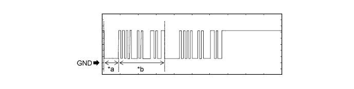
| *a | Approximately 160 ms | *b | Approximately 510 ms |
| Item | Content |
| Tester Connection | H22-5 (EFII) - H22-8 (GND) |
| Tool Setting | 2 V/DIV., 200 ms./DIV. |
| Condition | Within 3 seconds of hybrid control system start or within 3 seconds of power switch turned on (IG) after auxiliary battery cable disconnected and reconnected |
Waveform 2 (Reference)
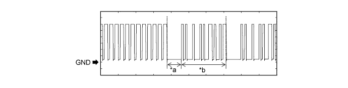
| *a | Approximately 160 ms | *b | Approximately 510 ms |
| Item | Content |
| Tester Connection | H22-6 (EFIO) - H22-8 (GND) |
| Tool Setting | 2 V/DIV., 200 ms./DIV. |
| Condition | Power switch on (IG) |
| CHECK TRANSMISSION CONTROL ECU ASSEMBLY |

Disconnect the A21 and A22 ECU connectors.
Measure the voltage and resistance according to the value(s) in the table below.
| Tester Connection | Input/Output | Wiring Color | Terminal Description | Condition | Specified Condition | Related Data List Item/DTC |
| A22-1 (E1) - Body ground | - | BR - Body ground | Ground | Always | Below 1 Ω | - |
| A22-5 (E02) - Body ground | - | W-B - Body ground | Ground | Always | Below 1 Ω | - |
| A22-6 (E01) - Body ground | - | W-B - Body ground | Ground | Always | Below 1 Ω | - |
| A21-16 (+B) - Body ground | Input | GR - Body ground | +B power supply | Power switch off | 11 to 14 V | - |
| A21-15 (BATT) - Body ground | Input | SB - Body ground | +B power supply | Power switch off | 11 to 14 V | - |
| CHECK POWER MANAGEMENT CONTROL ECU |
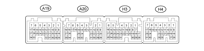
Measure the voltage according to the value(s) in the table below.
| Terminal No. (Symbol) | Input/Output | Wiring Color | Terminal Description | Condition | Specified Condition | Related Data List Item/DTC |
| A19-2 (+B2) - H3-5 (E01) | Input | L - W-B | Ignition power supply | Power switch on (IG) | 11 to 14 V | - |
| A20-5 (+B1) - H3-5 (E01) | Input | L - W-B | Ignition power supply | Power switch on (IG) | 11 to 14 V | - |
| A20-6 (MREL) - H3-5 (E01) | Input | BE - W-B | Ignition power supply | Power switch on (IG) | 11 to 14 V | - |
| H3-1 (AM22) - H3-6 (E1) | Input | W - W-B | +B power supply | Power switch off | 11 to 14 V | - |
| H3-5 (E01) - Body ground | - | W-B - Body ground | Ground | Always | Below 1 Ω | - |
| H3-6 (E1) - Body ground | - | W-B - Body ground | Ground | Always | Below 1 Ω | - |
| H4-4 (E12) - Body ground | - | W-B - Body ground | Ground | Always | Below 1 Ω | - |
| H4-5 (E02) - Body ground | - | W-B - Body ground | Ground | Always | Below 1 Ω | - |
| H4-7 (AM21) - H3-6 (E1) | Input | W - W-B | +B power supply | Power switch off | 11 to 14 V | - |
| H4-20 (IMO) - H3-6 (E1) | Input | L - W-B | ID code box (immobiliser code ECU) communication input | Power switch off | 11 to 14 V | - |
| H4-20 (IMO) - H3-6 (E1) | Input | L - W-B | ID code box (immobiliser code ECU) communication input | Within 3 seconds of hybrid control system start or within 3 seconds of power switch turned on (IG) after auxiliary battery cable disconnected and reconnected | Pulse generation (See waveform 1) | - |
| H4-21 (IMI) - H3-6 (E1) | Output | R - W-B | ID code box (immobiliser code ECU) communication output | Power switch off | 11 to 14 V | - |
| H4-21 (IMI) - H3-6 (E1) | Output | R - W-B | ID code box (immobiliser code ECU) communication output | Power switch on (IG) | Pulse generation (See waveform 2) | - |
Inspect using an oscilloscope.
Waveform 1 (Reference)
| *a | Approximately 160 ms | *b | Approximately 510 ms |
| Item | Content |
| Tester Connection | H4-20 (IMO) - H3-6 (E1) |
| Tool Setting | 2 V/DIV., 200 ms./DIV. |
| Condition | Within 3 seconds of hybrid control system start or within 3 seconds of power switch turned on (IG) after auxiliary battery cable disconnected and reconnected |
Waveform 2 (Reference)
| *a | Approximately 160 ms | *b | Approximately 510 ms |
| Item | Content |
| Tester Connection | H4-21 (IMI) - H3-6 (E1) |
| Tool Setting | 2 V/DIV., 200 ms./DIV. |
| Condition | Power switch on (IG) |
