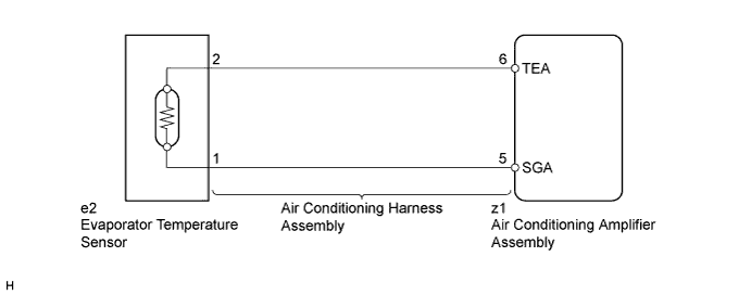
DTC B1413/13 Evaporator Temperature Sensor Circuit |
| DTC No. | DTC Detection Condition | Trouble Area |
| B1413/13 | Open or short in evaporator temperature sensor circuit |
|
| 1.READ VALUE USING INTELLIGENT TESTER |
Connect the intelligent tester to the DLC3.
Turn the power switch on (IG).
Turn the intelligent tester on.
Enter the following menus: Body / Air Conditioner / Data List.
Check the value(s) by referring to the table below.
| Tester Display | Measurement Item/Range | Normal Condition | Diagnostic Note |
| Evaporator Fin Thermistor | Evaporator temperature sensor / Min.: -29.7°C (-21.46°F) Max.: 59.55°C (139.19°F) | Actual evaporator temperature displayed | - |
| Result | Proceed to |
| NG | A |
| OK (When troubleshooting according to Problem Symptoms Table) | B |
| OK (When troubleshooting according to the DTC) | C |
|
| ||||
|
| ||||
| A | |
 |
| 2.INSPECT EVAPORATOR TEMPERATURE SENSOR |
Remove the evaporator temperature sensor.
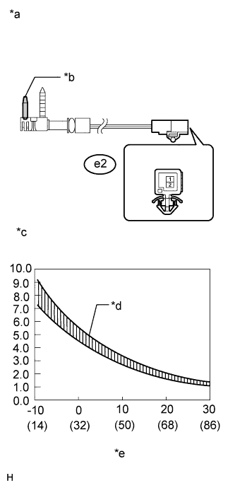 |
Disconnect the e2 evaporator temperature sensor connector.
Measure the resistance according to the value(s) in the table below.
| Tester Connection | Condition | Specified Condition |
| e2-1 - e2-2 | -10°C (14°F) | 7.30 to 9.10 kΩ |
| e2-1 - e2-2 | -5°C (23°F) | 5.65 to 6.95 kΩ |
| e2-1 - e2-2 | 0°C (32°F) | 4.40 to 5.35 kΩ |
| e2-1 - e2-2 | 5°C (41°F) | 3.40 to 4.15 kΩ |
| e2-1 - e2-2 | 10°C (50°F) | 2.70 to 3.25 kΩ |
| e2-1 - e2-2 | 15°C (59°F) | 2.14 to 2.58 kΩ |
| e2-1 - e2-2 | 20°C (68°F) | 1.71 to 2.05 kΩ |
| e2-1 - e2-2 | 25°C (77°F) | 1.38 to 1.64 kΩ |
| e2-1 - e2-2 | 30°C (86°F) | 1.11 to 1.32 kΩ |
| *a | Component without harness connected (Evaporator Temperature Sensor) |
| *b | Sensing Portion |
| *c | Resistance (kΩ) |
| *d | Allowable Range |
| *e | Temperature (°C (°F)) |
|
| ||||
| OK | |
|
| 3.INSPECT AIR CONDITIONING HARNESS ASSEMBLY (AIR CONDITIONING AMPLIFIER - EVAPORATOR TEMPERATURE SENSOR) |
Remove the air conditioning harness assembly (Click here).
Measure the resistance according to the value(s) in the table below.
| Tester Connection | Condition | Specified Condition |
| z1-6 (TEA) - e2-2 | Always | Below 1 Ω |
| z1-5 (SGA) - e2-1 | Always | Below 1 Ω |
| z1-6 (TEA) - Body ground | Always | 10 kΩ or higher |
| z1-5 (SGA) - Body ground | Always | 10 kΩ or higher |
|
| ||||
| OK | ||
 | ||
| ||

