DTC    B1423/23    Pressure Sensor Circuit

for Preparation Click here


DESCRIPTION

This DTC is stored when refrigerant pressure on the high pressure side is extremely low (0.19 MPa (2.0 kgf/cm2, 28 psi) or less) or extremely high (3.14 MPa (32.0 kgf/cm2, 455 psi) or more). The air conditioning pressure sensor is installed on the high pressure line. It detects refrigerant pressure to output a refrigerant pressure signal to the air conditioning amplifier assembly. The air conditioning amplifier assembly converts this signal to a pressure value according to the sensor characteristics to control the compressor.

DTC No.
DTC Detection Condition
Trouble Area
B1423/23
  1. Open or short in pressure sensor circuit
  2. Refrigerant pressure on the high pressure line is extremely low (0.19 MPa (2.0 kgf/cm2, 28 psi) or less) or extremely high (3.14 MPa (32.0 kgf/cm2, 455 psi) or more).
  1. Air conditioning pressure sensor
  2. Harness or connector between air conditioning pressure sensor and air conditioning amplifier assembly
  3. Air conditioning amplifier assembly
  4. Expansion valve (blocked, stuck)
  5. Cooler condenser assembly (blocked, deterioration of cooling capacity due to dirt)
  6. Cooler dryer (moisture in the refrigerant cycle cannot be absorbed)
  7. Cooling fan system (condenser cannot be cooled down)
  8. A/C system (leaks, blocked)

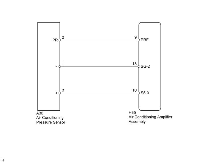
WIRING DIAGRAM


E219967E08


INSPECTION PROCEDURE

1.CHECK HARNESS AND CONNECTOR (POWER SOURCE CIRCUIT)
  1. Disconnect the A30 air conditioning pressure sensor connector.
  1. Measure the voltage according to the value(s) in the table below.

    Standard Voltage:
    Tester Connection
    Switch Condition
    Specified Condition
    A30-3 (+) - Body ground
    Power switch on (IG)
    4.75 to 5.25 V


NG
Go to step 5
OK


2.CHECK HARNESS AND CONNECTOR (GROUND CIRCUIT)
  1. Measure the resistance according to the value(s) in the table below.

    Standard Resistance:
    Tester Connection
    Condition
    Specified Condition
    A30-1 (-) - Body ground
    Always
    Below 1 Ω


NG
Go to step 6
OK


3.INSPECT AIR CONDITIONING PRESSURE SENSOR (SENSOR SIGNAL CIRCUIT)
  1. Reconnect the A30 air conditioning pressure sensor connector.


    E221023E06
  1. Remove the air conditioning amplifier assembly with the connectors still connected.

  1. Measure the voltage according to the value(s) in the table below.

    Standard Voltage:
    Tester Connection
    Condition
    Specified Condition
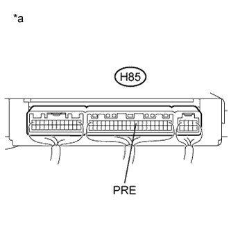
    H85-9 (PRE) - Body ground
    Power switch on (IG)
    (A/C switch: off)
    0.65 to 4.88 V

    HINT:
    If the voltage is not as specified, there may be a malfunction in the air conditioning amplifier assembly, air conditioning pressure sensor or wire harness. It is also possible that the amount of refrigerant may not be appropriate.

    Text in Illustration 
    *a
    Component with harness connected
    (Air Conditioning Amplifier Assembly)


NG
Go to step 7
OK


4.INSPECT AIR CONDITIONING PRESSURE SENSOR (SENSOR SIGNAL CIRCUIT)


  1. Measure the voltage when the following conditions are met:

    Item
    Condition
    Vehicle Doors
    Fully open
    Compressor speed
    5200 rpm
    Temperature Setting
    MAX COLD
    Blower Speed
    HI
    A/C Switch
    on
    R/F Switch
    RECIRCULATION
    Interior Temperature
    25 to 35°C (77 to 95°F)

    NOTICE:
    1. If refrigerant pressure in the high pressure line becomes extremely high during the inspection (if the voltage exceeds 4.84 V), the fail-safe function stops compressor operation. Therefore, measure the voltage before the fail-safe function operates.
    2. It is necessary to measure the voltage over a period of time (approximately 10 minutes) because the problem symptom may recur after a while.

    HINT:
    When the outside air temperature is low (below -1.5°C (29.3°F)), the compressor stops due to signals from the ambient temperature sensor and the evaporator temperature sensor to prevent the evaporator from freezing. In this case, perform the inspection in a warm indoor environment.


      E221023E07
    1. Measure the voltage according to the value(s) in the table below.

      Standard Voltage:
      Tester Connection
      Condition
      Specified Condition
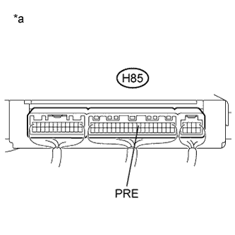
      H85-9 (PRE) - Body ground
      Power switch on (IG)
      (A/C: on)
      0.65 to 4.88 V

      Result:
      Result
      Proceed to
      OK (When troubleshooting according to the DTC)
      A
      OK (When troubleshooting according to Problem Symptoms Table)
      B
      NG
      C

      Text in Illustration 
      *a
      Component with harness connected
      (Air Conditioning Amplifier Assembly)


B
PROCEED TO NEXT SUSPECTED AREA SHOWN IN PROBLEM SYMPTOMS TABLE (Click here)

C
Go to step 13
A

REPLACE AIR CONDITIONING AMPLIFIER ASSEMBLY (Click here)  

5.CHECK HARNESS AND CONNECTOR (AIR CONDITIONING AMPLIFIER - A/C PRESSURE SENSOR)
  1. Disconnect the H85 air conditioning amplifier assembly connector.

  1. Measure the resistance according to the value(s) in the table below.

    Standard Resistance:
    Tester Connection
    Condition
    Specified Condition
    A30-3 (+) - H85-10 (S5-3)
    Always
    Below 1 Ω
    H85-10 (S5-3) - Body ground
    Always
    10 kΩ or higher


NG
REPAIR OR REPLACE HARNESS OR CONNECTOR
OK

REPLACE AIR CONDITIONING AMPLIFIER ASSEMBLY (Click here)  

6.CHECK HARNESS AND CONNECTOR (AIR CONDITIONING AMPLIFIER - A/C PRESSURE SENSOR)
  1. Disconnect the H85 air conditioning amplifier assembly connector.

  1. Measure the resistance according to the value(s) in the table below.

    Standard Resistance:
    Tester Connection
    Condition
    Specified Condition
    A30-1 (-) - H85-13 (SG-2)
    Always
    Below 1 Ω
    H85-13 (SG-2) - Body ground
    Always
    10 kΩ or higher


NG
REPAIR OR REPLACE HARNESS OR CONNECTOR
OK

REPLACE AIR CONDITIONING AMPLIFIER ASSEMBLY (Click here)  

7.CHECK HARNESS AND CONNECTOR (AIR CONDITIONING AMPLIFIER - A/C PRESSURE SENSOR)
  1. Disconnect the H85 air conditioning amplifier assembly connector.

  1. Measure the resistance according to the value(s) in the table below.

    Standard Resistance:
    Tester Connection
    Condition
    Specified Condition
    A30-2 (PR) - H85-9 (PRE)
    Always
    Below 1 Ω
    A30-2 (PR) - Body ground
    Always
    10 kΩ or higher


NG
REPAIR OR REPLACE HARNESS OR CONNECTOR
OK


8.CHECK FOR A/C SYSTEM LEAK
  1. Install the manifold gauge set.

  1. Recover the refrigerant from the A/C system using a refrigerant recovery unit.

  1. Evacuate the A/C system and check that vacuum can be maintained.

    OK:
    Vacuum can be maintained in the A/C system.

    HINT:
    If vacuum cannot be maintained in the A/C system, there may be a refrigerant leak. In this case, it is necessary to repair or replace the leaking part of the A/C system.


NG
Go to step 12
OK


9.CHARGE REFRIGERANT
  1. Add an appropriate amount of refrigerant (Click here).


NEXT


10.RECHECK FOR DTC
  1. Recheck for the DTC when the following conditions are met:

    Item
    Condition
    Vehicle Doors
    Fully open
    Compressor Speed
    5200 rpm
    Temperature Setting
    MAX COLD
    Blower Speed
    HI
    A/C Switch
    on
    R/F Switch
    RECIRCULATION
    Interior Temperature
    25 to 35°C (77 to 95°F)

    NOTICE:
    If refrigerant pressure in the high pressure line is excessive, this DTC will be stored. Therefore, it is necessary to measure the voltage over a period of time (approximately 10 minutes) because this DTC may be stored after the A/C has been operating for a while.

    HINT:
    When the outside air temperature is low (below -1.5°C (29.3°F)), the compressor stops due to signals from the ambient temperature sensor and the evaporator temperature sensor to prevent the evaporator from freezing. In this case, perform the inspection in a warm indoor environment.

    Result:
    Result
    Proceed to
    DTC B1423/23 is output
    A
    DTC B1423/23 is not output
    B

    NOTICE:
    If the DTC was stored due to an insufficient or excessive amount of refrigerant, the problem may have been solved after performing the previous step. However, the root cause of insufficient refrigerant may be refrigerant leaks. The root cause of excessive refrigerant may be adding refrigerant when the level was insufficient. Therefore, identify and repair any refrigerant leaks as necessary.


B
END
A


11.INSPECT AIR CONDITIONING PRESSURE SENSOR
  1. Install the manifold gauge set.

  1. Reconnect the air conditioning pressure sensor connector.

  1. Turn the power switch on (IG).


    E224399E01
  1. Measure the voltage according to the value(s) in the table below.

    Standard Voltage:
    Tester Connection
    Condition
    Specified Condition
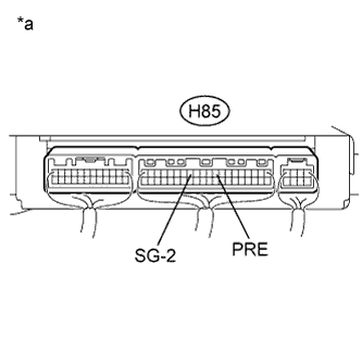
    H85-9 (PRE) - H85-13 (SG-2)
    Refrigerant pressure:
    Normal pressure (less than 3.187 MPa [462 psi] and more than 0.39 MPa [57 psi])
    0.92 to 4.94 V

    HINT:
    The air conditioning pressure sensor power source voltage is 5 V.

    Text in Illustration 
    *a
    Component with harness connected
    (Air Conditioning Amplifier Assembly)


NG
Go to step 19
OK

REPLACE AIR CONDITIONING AMPLIFIER ASSEMBLY (Click here)  

12.REPAIR A/C SYSTEM LEAK
  1. Identify the area where refrigerant leaks from (Click here).

  1. Repair the identified area of the A/C system.

  1. Evacuate the A/C system.


NEXT

CHARGE REFRIGERANT (Click here)  

13.INSPECT COOLING FAN SYSTEM
  1. Check that the cooling fan(s) operates normally.

    HINT:
    Refer to Cooling Fan Circuit (Click here).


NG
REPAIR COOLING FAN SYSTEM
OK


14.CHARGE REFRIGERANT
  1. Use a refrigerant recovery unit to recover refrigerant.

  1. Evacuate the A/C system.

  1. Add an appropriate amount of refrigerant (Click here).

    HINT:
    If refrigerant is added and the system has not been properly evacuated (insufficient vacuum time), moisture in the air remaining in the system will freeze in the expansion valve, blocking the flow on the high pressure side. Therefore, recover the refrigerant and properly evacuate the system. Add an appropriate amount of refrigerant, and check for DTCs.


NEXT


15.RECHECK FOR DTC
  1. Recheck for the DTC when the following conditions are met:

    Item
    Condition
    Vehicle Doors
    Fully open
    Compressor Speed
    5200 rpm
    Temperature Setting
    MAX COLD
    Blower Speed
    HI
    A/C Switch
    on
    R/F Switch
    RECIRCULATION
    Interior Temperature
    25 to 35°C (77 to 95°F)

    NOTICE:
    If refrigerant pressure in the high pressure line is excessive, this DTC will be stored. Therefore, it is necessary to measure the voltage over a period of time (approximately 10 minutes) because DTC may be stored after the A/C has been operating for a while.

    HINT:
    1. When the outside air temperature is low (below -1.5°C (29.3°F)), the compressor stops due to signals from the ambient temperature sensor and the evaporator temperature sensor to prevent the evaporator from freezing. In this case, perform the inspection in a warm indoor environment.
    2. If refrigerant is added and the system has not been properly evacuated (insufficient vacuum time), moisture in the air remaining in the system will freeze in the expansion valve, blocking the flow on the high pressure side. Therefore, recover the refrigerant and properly evacuate the system. Add an appropriate amount of refrigerant, and check for the DTC. If the DTC is not output, it indicates that the cooler dryer in the condenser is not able to absorb moisture in the refrigerant. In this case, to complete the repair, it is necessary to replace the cooler dryer.

    Result:
    Result
    Proceed to
    DTC B1423/23 is output
    A
    DTC B1423/23 is not output
    B


B
REPLACE COOLER DRYER (Click here)
A


16.REPLACE EXPANSION VALVE
  1. Replace the expansion valve with a new or a known good one (Click here).

    HINT:
    Replace the expansion valve with a new or a known good one because the expansion valve is either stuck or clogged.


NEXT


17.CHARGE REFRIGERANT
  1. Add an appropriate amount of refrigerant (Click here).


NEXT


18.RECHECK FOR DTC
  1. Recheck for the DTC when the following conditions are met:

    Item
    Condition
    Vehicle Doors
    Fully open
    Compressor Speed
    5200 rpm
    Temperature Setting
    MAX COLD
    Blower Speed
    HI
    A/C Switch
    on
    R/F Switch
    RECIRCULATION
    Interior Temperature
    25 to 35°C (77 to 95°F)

    NOTICE:
    If refrigerant pressure in the high pressure line is excessive, this DTC will be stored. Therefore, it is necessary to measure the voltage over a period of time (approximately 10 minutes) because this DTC may be stored after the A/C has been operating for a while.

    HINT:
    1. When the outside air temperature is low (below -1.5°C (29.3°F)), the compressor stops due to signals from the ambient temperature sensor and the evaporator temperature sensor to prevent the evaporator from freezing. In this case, perform the inspection in a warm indoor environment.
    2. If refrigerant pressure is not normal after replacing the expansion valve with a new or a known good one, the condenser or pipes may be clogged with dirt, dust or other contaminants. In this case, clean or replace the condenser or pipes.

    Result:
    Result
    Proceed to
    DTC B1423/23 is not output
    A
    DTC B1423/23 is output
    B


B
REPLACE COOLER CONDENSER ASSEMBLY (Click here)
A

END 

19.REPLACE AIR CONDITIONING PRESSURE SENSOR
  1. Replace the air conditioning pressure sensor (Click here).

    HINT:
    Since the air conditioning pressure sensor cannot be inspected while it is removed from the vehicle, replace the air conditioning pressure sensor with a new or a known good one and check that the condition returns to normal.


NEXT


20.RECHECK FOR DTC
  1. Recheck for the DTC when the following conditions are met:

    Item
    Condition
    Vehicle Doors
    Fully open
    Compressor Speed
    5200 rpm
    Temperature Setting
    MAX COLD
    Blower Speed
    HI
    A/C Switch
    on
    R/F Switch
    RECIRCULATION
    Interior Temperature
    25 to 35°C (77 to 95°F)

    NOTICE:
    If refrigerant pressure in the high pressure line is excessive, this DTC will be stored. Therefore, it is necessary to measure the voltage over a period of time (approximately 10 minutes) because this DTC may be stored after the A/C has been operating for a while.

    HINT:
    When the outside air temperature is low (below -1.5°C (29.3°F)), the compressor stops due to signals from the ambient temperature sensor and the evaporator temperature sensor to prevent the evaporator from freezing. In this case, perform the inspection in a warm indoor environment.

    Result:
    Result
    Proceed to
    DTC B1423/23 is not output
    A
    DTC B1423/23 is output
    B


B
REPLACE AIR CONDITIONING AMPLIFIER ASSEMBLY (Click here)
A

END