FRONT POWER SEAT CONTROL SYSTEM (w/ Memory) > TERMINALS OF ECU |
| CHECK POSITION CONTROL ECU AND SWITCH ASSEMBLY |
for LHD:
Disconnect the X4 and X5 connectors from the position control ECU and switch assembly.

Measure the voltage and resistance according to the value(s) in the table below.
| Terminal No. (Symbol) | Wiring Color | Terminal Description | Condition | Specified Condition |
| X4-2 (GND) - Body ground | W-B - Body ground | Ground | Always | Below 1 Ω |
| X4-7 (+B) - X4-2 (GND) | W - W-B | Power source | Power switch off | 11 to 14 V |
| X5-12 (SYSB) - X4-2 (GND) | P - W-B | System power source | Power switch off | 11 to 14 V |
Reconnect the X4 and X5 connectors to the position control ECU and switch assembly.
Measure the voltage and resistance according to the value(s) in the table below.
| Terminal No. (Symbol) | Wiring Color | Terminal Description | Condition | Specified Condition |
| X4-6 (+B2) - X4-1 (GND2) | SB - W-B | Lumbar support adjuster power source | Power switch off | 11 to 14 V |
| X4-1 (GND2) - Body ground | W-B - Body ground | Lumbar support adjuster ground | Always | Below 1 Ω |
| X4-3 (SLD+) - X4-2 (GND) | L - W-B | Sliding motor signal (forward) | Slide switch off | Below 1 V |
| Slide switch on (Forward) | 11 to 14 V | |||
| X4-4 (SLD-) - X4-2 (GND) | GR - W-B | Sliding motor signal (rearward) | Slide switch off | Below 1 V |
| Slide switch on (Rearward) | 11 to 14 V | |||
| X4-5 (FRV-) - X4-2 (GND) | R - W-B | Front vertical motor signal (downward) | Front vertical switch off | Below 1 V |
| Front vertical switch on (Downward) | 11 to 14 V | |||
| X4-8 (FRV+) - X4-2 (GND) | B - W-B | Front vertical motor signal (upward) | Front vertical switch off | Below 1 V |
| Front vertical switch on (Upward) | 11 to 14 V | |||
| X4-9 (RCL+) - X4-2 (GND) | P - W-B | Reclining motor signal (forward) | Reclining switch off | Below 1 V |
| Reclining switch on (Forward) | 11 to 14 V | |||
| X4-11 (RCL-) - X4-2 (GND) | LG - W-B | Reclining motor signal (rearward) | Reclining switch off | Below 1 V |
| Reclining switch on (Rearward) | 11 to 14 V | |||
| X4-10 (LFT+) - X4-2 (GND) | V - W-B | Lifter motor signal (upward) | Lifter switch off | Below 1 V |
| Lifter switch on (Upward) | 11 to 14 V | |||
| X4-12 (LFT-) - X4-2 (GND) | G - W-B | Lifter motor signal (downward) | Lifter switch off | Below 1 V |
| Lifter switch on (Downward) | 11 to 14 V | |||
| X5-1 (SGND) - X4-2 (GND) | BR - W-B | Position sensor ground | Always | Below 1 Ω |
| X5-3 (SSFV) - X5-1 (SGND) | R - BR | Front vertical position signal | Front vertical function operating | 4.5 to 4.8 V |
| X5-4 (SSRL) - X5-1 (SGND) | P - BR | Lifter position signal | Lifter function operating | 4.5 to 4.8 V |
| X5-5 (SSRS) - X5-1 (SGND) | G- BR | Slide position signal | Slide function operating | 4.5 to 4.8 V |
| X5-11 (SSRR) - X5-1 (SGND) | V - BR | Reclining position signal | Reclining function operating | 4.5 to 4.8 V |
for RHD:
Disconnect the W3 and W4 connectors from the position control ECU and switch assembly.

Measure the voltage and resistance according to the value(s) in the table below.
| Terminal No. (Symbol) | Wiring Color | Terminal Description | Condition | Specified Condition |
| W3-2 (GND) - Body ground | W-B - Body ground | Ground | Always | Below 1 Ω |
| W3-7 (+B) - W3-2 (GND) | W - W-B | Power source | Power switch off | 11 to 14 V |
| W4-12 (SYSB) - W3-2 (GND) | P - W-B | System power source | Power switch off | 11 to 14 V |
Reconnect the W3 and W4 connectors to the position control ECU and switch assembly.
Measure the voltage and resistance according to the value(s) in the table below.
| Terminal No. (Symbol) | Wiring Color | Terminal Description | Condition | Specified Condition |
| W3-6 (+B2) - W3-1 (GND2) | SB - W-B | Lumbar support adjuster power source | Power switch off | 11 to 14 V |
| W3-1 (GND2) - Body ground | W-B - Body ground | Lumbar support adjuster ground | Always | Below 1 Ω |
| W3-3 (SLD+) - W3-2 (GND) | L - W-B | Sliding motor signal (forward) | Slide switch off | Below 1 V |
| Slide switch on (Forward) | 11 to 14 V | |||
| W3-4 (SLD-) - W3-2 (GND) | GR - W-B | Sliding motor signal (rearward) | Slide switch off | Below 1 V |
| Slide switch on (Rearward) | 11 to 14 V | |||
| W3-5 (FRV-) - W3-2 (GND) | R - W-B | Front vertical motor signal (downward) | Front vertical switch off | Below 1 V |
| Front vertical switch on (Downward) | 11 to 14 V | |||
| W3-8 (FRV+) - W3-2 (GND) | B - W-B | Front vertical motor signal (upward) | Front vertical switch off | Below 1 V |
| Front vertical switch on (Upward) | 11 to 14 V | |||
| W3-9 (RCL+) - W3-2 (GND) | P - W-B | Reclining motor signal (forward) | Reclining switch off | Below 1 V |
| Reclining switch on (Forward) | 11 to 14 V | |||
| W3-11 (RCL-) - W3-2 (GND) | LG - W-B | Reclining motor signal (rearward) | Reclining switch off | Below 1 V |
| Reclining switch on (Rearward) | 11 to 14 V | |||
| W3-10 (LFT+) - W3-2 (GND) | V - W-B | Lifter motor signal (upward) | Lifter switch off | Below 1 V |
| Lifter switch on (Upward) | 11 to 14 V | |||
| W3-12 (LFT-) - W3-2 (GND) | G - W-B | Lifter motor signal (downward) | Lifter switch off | Below 1 V |
| Lifter switch on (Downward) | 11 to 14 V | |||
| W4-1 (SGND) - W3-2 (GND) | BR - W-B | Position sensor round | Always | Below 1 Ω |
| W4-3 (SSFV) - W4-1 (SGND) | R - BR | Front vertical position signal | Front vertical function operating | 4.5 to 4.8 V |
| W4-4 (SSRL) - W4-1 (SGND) | P - BR | Lifter position signal | Lifter function operating | 4.5 to 4.8 V |
| W4-5 (SSRS) - W4-1 (SGND) | G- BR | Slide position signal | Slide function operating | 4.5 to 4.8 V |
| W4-11 (SSRR) - W4-1 (SGND) | V - BR | Reclining position signal | Reclining function operating | 4.5 to 4.8 V |
| CHECK OUTER MIRROR CONTROL ECU ASSEMBLY (for Driver Side) |
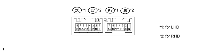
for LHD:
Disconnect the K7 connector from the outer mirror control ECU assembly (for driver side).
Measure the voltage and resistance according to the value(s) in the table below.
| Tester Connection | Wiring Color | Terminal Description | Condition | Specified Condition |
| K7-7 (GND) - Body ground | W-B - Body ground | Ground | Always | Below 1 Ω |
| K7-14 (BDR) - K7-7 (GND) | L - W-B | Power source | Power switch off | 11 to 14 V |
| K7-5 (SIG) - K7-7 (GND) | Y - W-B | Power source (IG) | Power switch off | Below 1 V |
| Power switch on (IG) | 11 to 14 V | |||
| K7-6 (CPUB) - K7-7 (GND) | LG - W-B | Power source | Power switch off | 11 to 14 V |
Reconnect the K7 connector to the outer mirror control ECU assembly (for driver side).
Measure the voltage according to the value(s) in the table below.
| Tester Connection | Wiring Color | Terminal Description | Condition | Specified Condition |
| K7-4 (M3) - K7-13 (MSWE) | G - W | M3 switch signal for seat memory switch | M3 switch on | Below 1 V |
| M3 switch off | 11 to 14 V | |||
| K7-3 (M2) - K7-13 (MSWE) | L - W | M2 switch signal for seat memory switch | M2 switch on | Below 1 V |
| M2 switch off | 11 to 14 V | |||
| K7-2 (M1) - K7-13 (MSWE) | R - W | M1 switch signal for seat memory switch | M1 switch on | Below 1 V |
| M1 switch off | 11 to 14 V | |||
| K7-1 (MM) - K7-13 (MSWE) | SB - W | SET switch signal for seat memory switch | SET switch on | Below 1 V |
| SET switch off | 11 to 14 V |
for RHD:
Disconnect the J8 connector from the outer mirror control ECU assembly (for driver side).
Measure the voltage and resistance according to the value(s) in the table below.
| Tester Connection | Wiring Color | Terminal Description | Condition | Specified Condition |
| J8-7 (GND) - Body ground | W-B - Body ground | Ground | Always | Below 1 Ω |
| J8-14 (BDR) - J8-7 (GND) | L - W-B | Power source | Power switch off | 11 to 14 V |
| J8-5 (SIG) - J8-7 (GND) | Y - W-B | Power source (IG) | Power switch off | Below 1 V |
| Power switch on (IG) | 11 to 14 V | |||
| J8-6 (CPUB) - J8-7 (GND) | LG - W-B | Power source | Power switch off | 11 to 14 V |
Reconnect the J8 connector to the outer mirror control ECU assembly (for driver side).
Measure the voltage according to the value(s) in the table below.
| Tester Connection | Wiring Color | Terminal Description | Condition | Specified Condition |
| J8-4 (M3) - J8-13 (MSWE) | G - W | M3 switch signal for seat memory switch | M3 switch on | Below 1 V |
| M3 switch off | 11 to 14 V | |||
| J8-3 (M2) - J8-13 (MSWE) | R - W | M2 switch signal for seat memory switch | M2 switch on | Below 1 V |
| M2 switch off | 11 to 14 V | |||
| J8-2 (M1) - J8-13 (MSWE) | V - W | M1 switch signal for seat memory switch | M1 switch on | Below 1 V |
| M1 switch off | 11 to 14 V | |||
| J8-1 (MM) - J8-13 (MSWE) | SB - W | SET switch signal for seat memory switch | SET switch on | Below 1 V |
| SET switch off | 11 to 14 V |
| CHECK MAIN BODY ECU (MULTIPLEX NETWORK BODY ECU) |
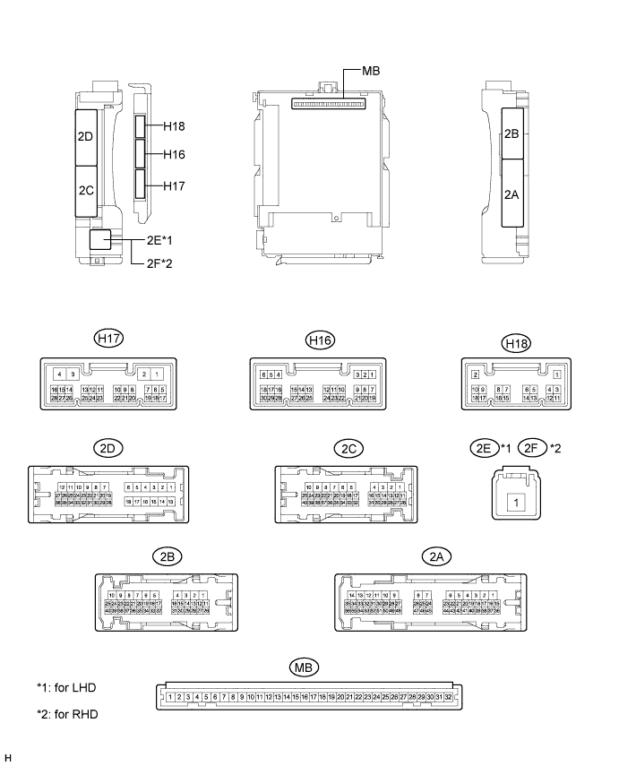
Disconnect the 2C, 2E*1, 2F*2 and 2B connectors from the instrument panel junction block assembly.
Measure the voltage and resistance according to the value(s) in the table below.
| Tester Connection | Wiring Color | Terminal Description | Condition | Specified Condition |
| 2C-18 - Body ground | B - Body ground | Power source | Power switch off | 11 to 14 V |
| 2E-1 - Body ground*1 2F-1 - Body ground*2 | W - Body ground | Power source (IG) | Power switch off | 11 to 14 V |
| 2B-6 - Body ground | W-B - Body ground | Body ground | Always | Below 1 Ω |
Reconnect the 2C, 2E and 2B instrument panel junction block assembly connectors.
Measure the voltage according to the value(s) in the table below.
| Tester Connection | Wiring Color | Terminal Description | Condition | Specified Condition |
| 2D-35 (FLCY) - Body ground*1 | BR - Body ground | Front door courtesy light switch assembly signal | Driver door closed | 11 to 14 V |
| Driver door open | Below 1 V | |||
| 2D-36 (FRCY) - Body ground*2 | BR - Body ground | Front door courtesy light switch assembly signal | Driver door closed | 11 to 14 V |
| Driver door open | Below 1 V |
